
Manual
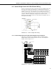

4WFBS120, 4WFBS350, 4WFBS1K 4 Wire Full Bridge Terminal Input Modules (TIM)
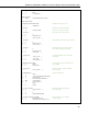
12: Average (P71)
1: 1 Reps
2: 1 Loc [ mVperV ]
13: If Flag/Port (P91) ;When average is calculated,
1: 10 Do if Output Flag is High (Flag 0) ;also send it to Final Storage
2: 10 Set Output Flag High
14: Set Active Storage Area (P80) ;Direct Output to Final Storage
1: 1 Final Storage Area 1
2: 11 Array ID ;set Array ID = 11 for zero data
15: Real Time (P77)
1: 110 Day,Hour/Minute
16: Sample (P70)
1: 1 Reps
2: 2 Loc [ mVperV_0 ]
17: End (P95)
18: End (P95)
End Program
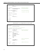
Example Program 4.5. 21X ¼ Bridge Strain with 1 rep and zero offset
;{21X}
*Table 1 Program
01: 1 Execution Interval (seconds)
;Other measurements could be inserted here or before the Output section
1: If Flag/Port (P91) ;On the first execution (Flag 1 is low)
1: 21 Do if Flag 1 is Low ;or when user sets Flag 1 low
2: 1 Call Subroutine 1 ;call the zeroing subroutine
2: Full Bridge (P6) ;Measure the strain gage
1: 1 Reps
2: 2 ± 15 mV Slow Range
3: 1 DIFF Channel
4: 1 Excite all reps withExchan 1
5: 5000 mV Excitation
6: 1 Loc [ mVperV ]
7: 1 Mult
8: 0 Offset
3: Z=X-Y (P35) ;Subtract zero reading from the
1: 1 X Loc [ mVperV ] ;measurement
2: 2 Y Loc [ mVperV_0 ]
3: 3 Z Loc [ Vr ]
4: Z=X*F (P37) ;Change Vr from mV/V to V/V
1: 3 X Loc [ Vr ]
2: 0.001 F
3: 3 Z Loc [ Vr ]
14