
Owner's manual
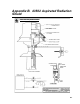
Table Of Contents
- Revision and Copyright Information
- Warranty
- Assistance
- Table of Contents
- 1. General
- 2. Specifications
- 3. Installation
- 4. Wiring
- 5. Datalogger Programming for the 43347-VX Probe
- 6. 43347-IX Measurement using Current Excitation
- 7. Maintenance
- 8. 43347 RTD Temperature Probe Calibration
- 9. Manufacturer’s Information
- 10. Troubleshooting
- 11. References
- Appendix A. Example CR10(X) Program for Ice Bath Calibration
- Appendix B. 43502 Aspirated Radiation Shield
- Appendix C. 43347 Aspirated Radiation Shield
- Appendix D. Measure Two 43347-IX Probes Using One Current Excitation Channel
- Campbell Scientific Companies

43347 RTD Temperature Probe, 43502 and 41003-5 Radiation Shields
other solvent. Check mounting bolts periodically for possible loosening due to
tower vibration.
8. 43347 RTD Temperature Probe Calibration
Calibration should be checked every 12 months. Probes used to measure a
temperature gradient should be checked with respect to absolute temperature,
and with respect to zero temperature difference. An excellent discussion on
calibration procedures can be found in the Quality Assurance Handbook for
Air Pollution Measurement Systems, Volume IV Meteorological
Measurements
1
.
9. Manufacturer’s Information
Refer to the RM Young 43502 Instruction Manual for additional information
such as replacement parts, assembly drawings, and electrical schematics.
10. Troubleshooting
-99999, NAN displayed in input location:
Make sure the temperature probe is connected to the correct input
channels (Section 5, Datalogger Programming for the 43347-VX Probe,
and Section 6, 43347-IX Measurement using Current Excitation). The
input channel (Instruction 9) refers to the channel that the black and
orange wires are connected to. The white and green wires connect to the
next (higher) contiguous channel.
Unreasonable value displayed in input location:
Make sure the multiplier and offset values entered for Instruction 9 are
correct. For calibrated temperature probes (Section 6.1, Wiring), make
sure the coefficients have been properly scaled and entered for Instruction
55. For uncalibrated temperature probes (Section 6.2, Datalogger
Programming), make sure the multiplier and offset values have been
properly entered for Instruction 16.
Temperature reading too high:
Make sure the blower is working properly and there are no obstructions to
the air flow in the sensor shield, telescoping arm, or vent holes. Also,
check that the probe end of the shield points toward the prevailing wind.
11. References
1
EPA, (1989). Quality Assurance Handbook for Air Pollution Measurement
Systems Volume IV - Meteorological Measurements, EPA Office of Research
and Development, Research Triangle Park, North Carolina 27711.
19