
Owner's manual
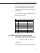

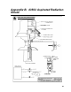
Table Of Contents
- Revision and Copyright Information
- Warranty
- Assistance
- Table of Contents
- 1. General
- 2. Specifications
- 3. Installation
- 4. Wiring
- 5. Datalogger Programming for the 43347-VX Probe
- 6. 43347-IX Measurement using Current Excitation
- 7. Maintenance
- 8. 43347 RTD Temperature Probe Calibration
- 9. Manufacturer’s Information
- 10. Troubleshooting
- 11. References
- Appendix A. Example CR10(X) Program for Ice Bath Calibration
- Appendix B. 43502 Aspirated Radiation Shield
- Appendix C. 43347 Aspirated Radiation Shield
- Appendix D. Measure Two 43347-IX Probes Using One Current Excitation Channel
- Campbell Scientific Companies

43347 RTD Temperature Probe, 43502 and 41003-5 Radiation Shields
The 43347-IX is measured with the Resistance measurement instruction with
the CR3000 and CR5000 dataloggers. The Resistance measurement applies a
switched current excitation and measures the voltage across the 1000 ohm
RTD. The result, with a multiplier of 1 and an offset of 0, is the RTD
resistance in ohms. The measurement result is converted to temperature with
the PRT instruction for uncalibrated probes, or with a polynomial equation for
calibrated probes. Calibrated probes include a calibration certificate with the
polynomial coefficients.
The Resistance and PRT Instructions with their parameters are listed below:
Resistance(Dest, Reps, Range, DiffChan, IexChan, MeasPEx, EXuA, RevEx,
RevDiff, SettlingTime, Integ, Mult, Offset)
PRT(Dest, Reps, Source, Mult, Offset)
TABLE 6-2 shows the sensor wiring for the measurement examples.
TABLE 6-2. Wiring for Measurement Examples
Color Function CR3000, CR5000
Red Switched Current Excitation IX1
White Differential High 1H
Green Differential Low 1L
Black Excitation Return IXR
Clear Shield
43502 Shield
White Tachometer
Red *12V power
Black *Gound
*wired to the 115 Vac/12 DC transformer supplied with the 43502,
or separate 12 Vdc supply
6.2.1 Datalogger Programming for Calibrated 43347–IX Probes
Calibrated 43347-IX probes are provided with a calibration certificate that
gives the relationship of resistance to temperature as Equation “T”, as shown in
the example below:
T = -250.052585 + R x 2.375187E-1 + R
2
x 1.258482E-5
The measurement result of the Resistance instruction (ohms) is converted to
temperature with a polynomial equation and the coefficients from equation
“T”, as shown below.
The following example program measures a calibrated 43347-IX probe every 1
second and stores a 15 minute average temperature in degrees Celsius.
15