
Owner's manual
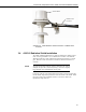
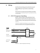
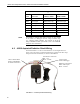
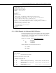
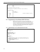
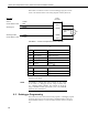
Table Of Contents
- Revision and Copyright Information
- Warranty
- Assistance
- Table of Contents
- 1. General
- 2. Specifications
- 3. Installation
- 4. Wiring
- 5. Datalogger Programming for the 43347-VX Probe
- 6. 43347-IX Measurement using Current Excitation
- 7. Maintenance
- 8. 43347 RTD Temperature Probe Calibration
- 9. Manufacturer’s Information
- 10. Troubleshooting
- 11. References
- Appendix A. Example CR10(X) Program for Ice Bath Calibration
- Appendix B. 43502 Aspirated Radiation Shield
- Appendix C. 43347 Aspirated Radiation Shield
- Appendix D. Measure Two 43347-IX Probes Using One Current Excitation Channel
- Campbell Scientific Companies

43347 RTD Temperature Probe, 43502 and 41003-5 Radiation Shields
5.2.2 CR10X Example for Uncalibrated 43347-VX Probes
;{CR10X}
;
*Table 1 Program
01: 5 Execution Interval (seconds)
;Measure the 43347 probe, result = Rs/Rf
1: Full Bridge w/mv Excit (P9)
1: 1 Reps
2: 24 250 mV 60 Hz Rejection Ex Range ;CR23X (200 mV); 21X,CR7 (500 mV)
3: 24 250 mV 60 Hz Rejection Br Range ;CR23X (200 mV); 21X,CR7 (500 mV)
4: 1 DIFF Channel
5: 1 Excite all reps w/Exchan 1
6: 2500 mV Excitation ;CR23X (2000 mV); 21X,CR7 (5000 mV)
7: 1 Loc [ RTD_C ]
8: 1 Mult
9: 0 Offset
;Convert measurement result to Temperature deg C
2: Temperature RTD (P16)
1: 1 Reps
2: 1 R/R0 Loc [ RTD_C ]
3: 1 Loc [ RTD_C ]
4: 1.0267 Mult ; (0.00385/0.00375)
5: 0 Offset
3: Pulse (P3)
1: 1 Reps
2: 6 Control Port 6
3: 20 High Frequency, Output Hz
4: 2 Loc [ Tach_Hz ]
5: 1.0 Multiplier
6: 0.0 Offset
6. 43347-IX Measurement using Current Excitation
The 43347-IX probe is measured with the Resistance measurement instruction
with the CR3000 and CR5000 dataloggers. The Resistance measurement
applies a switched current excitation and measures the voltage across the 1000
ohm RTD. Appendix D, Measure Two 43347-IX Probes Using One Current
Excitation Channel, shows how a single current excitation channel can be used
to excite as many as 25 43347 probes connected in series if the excitation
current is 170 μA. Details on determining the excitation current and other
parameter options are described in Section 6.3, Resistance Measurement
Instruction Details.
6.1 Wiring
The 43347-IX probe is configured as shown in FIGURE 6-1. Connections to
the CR3000 and CR5000 dataloggers are shown in TABLE 6-1.
13