
Owner's manual
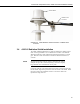
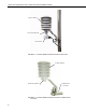
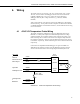
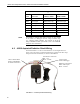
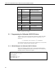
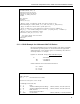
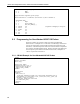
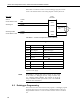
Table Of Contents
- Revision and Copyright Information
- Warranty
- Assistance
- Table of Contents
- 1. General
- 2. Specifications
- 3. Installation
- 4. Wiring
- 5. Datalogger Programming for the 43347-VX Probe
- 6. 43347-IX Measurement using Current Excitation
- 7. Maintenance
- 8. 43347 RTD Temperature Probe Calibration
- 9. Manufacturer’s Information
- 10. Troubleshooting
- 11. References
- Appendix A. Example CR10(X) Program for Ice Bath Calibration
- Appendix B. 43502 Aspirated Radiation Shield
- Appendix C. 43347 Aspirated Radiation Shield
- Appendix D. Measure Two 43347-IX Probes Using One Current Excitation Channel
- Campbell Scientific Companies
43347 RTD Temperature Probe, 43502 and 41003-5 Radiation Shields
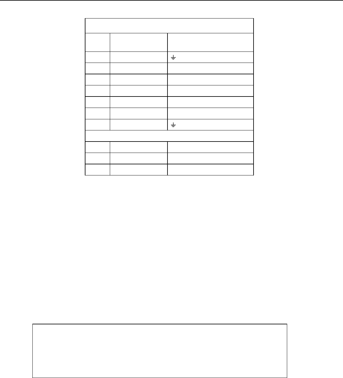
TABLE 5-1. Wiring for Measurement Examples
Color
Function
Datalogger Channels used for
Measurement Examples
Clear Shield (G) for CR10(X)
Red Switched Excitation E1
White Differential High 2H
Green Differential Low 2L
Black Differential High 1H
Orange Differential Low 1L
Purple Analog Reference (AG) for CR10(X)
43502 Shield
White Tachometer C1, C6 for CR10X
Red *12V Power
Black Ground
*wired to the 115 Vac/12 DC transformer supplied with the
43502, or separate 12 Vdc supply
5.1 Programming for Calibrated 43347-VX Probes
Calibrated 43347 probes are provided with a calibration certificate from R.M.
Young Co. that gives the relationship of resistance to temperature (°C) as
Equation “T”.
T = -250.052585 + R x 2.375187E-1 + R
2
x 1.258482E-5
The measurement result of the instruction with a multiplier of 1.0 and an offset
of 0.0 is R
s
/R
f
= the RTD resistance divided by 1000.
5.1.1 CR1000 Example for Calibrated 43347-VX Probes
Because the calibration coefficients are to convert sensor resistance (Rs) to
temperature, the BrHalf4W measurement result (Rs/Rf) must be multiplied by
1000 (Rf), before the coefficients are applied.
'CR1000
'Declare Variables and Units
Public RTD_Res
Public RTD_Cal_C
Units RTD_Cal_C = Deg C
Public 43502_Tach
Units 43502_Tach = Hz
10