
Owner's manual
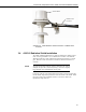
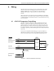
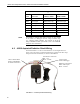
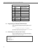
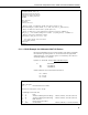
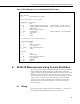
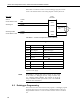
Table Of Contents
- Revision and Copyright Information
- Warranty
- Assistance
- Table of Contents
- 1. General
- 2. Specifications
- 3. Installation
- 4. Wiring
- 5. Datalogger Programming for the 43347-VX Probe
- 6. 43347-IX Measurement using Current Excitation
- 7. Maintenance
- 8. 43347 RTD Temperature Probe Calibration
- 9. Manufacturer’s Information
- 10. Troubleshooting
- 11. References
- Appendix A. Example CR10(X) Program for Ice Bath Calibration
- Appendix B. 43502 Aspirated Radiation Shield
- Appendix C. 43347 Aspirated Radiation Shield
- Appendix D. Measure Two 43347-IX Probes Using One Current Excitation Channel
- Campbell Scientific Companies
43347 RTD Temperature Probe, 43502 and 41003-5 Radiation Shields
TABLE 4-1. Datalogger Connections
Color
Wire Label
CR10(X), CR510
CR3000, CR1000,
CR800, CR5000
Red Volt Excite/+ RTD Switched Excitation Switched Excitation
White Sense Signal Differential (high) Differential (high)
Green Sense Signal Ref Differential (low) Differential (low)
Black RTD Signal/- RTD Differential (high) Differential (high)
Orange RTD Signal Ref Differential (low) Differential (low)
Purple Excitation Reference (AG)
Clear Shield G G
Occasionally, a customer may need to connect an “IX” version
of the sensor to a datalogger that has voltage excitation only
(e.g., CR10(X), CR800, CR1000). The customer can do this by
using a 4WPB1K terminal input module (refer to the 4WPB1K
manual for more information).
NOTE
4.2 43502 Aspirated Radiation Shield Wiring
The shield includes a 115 Vac/12 Vdc transformer. In most applications AC
power is run to the tower or tripod and terminated in a junction box that is large
enough to house the transformer(s) as shown in FIGURE 4-2.
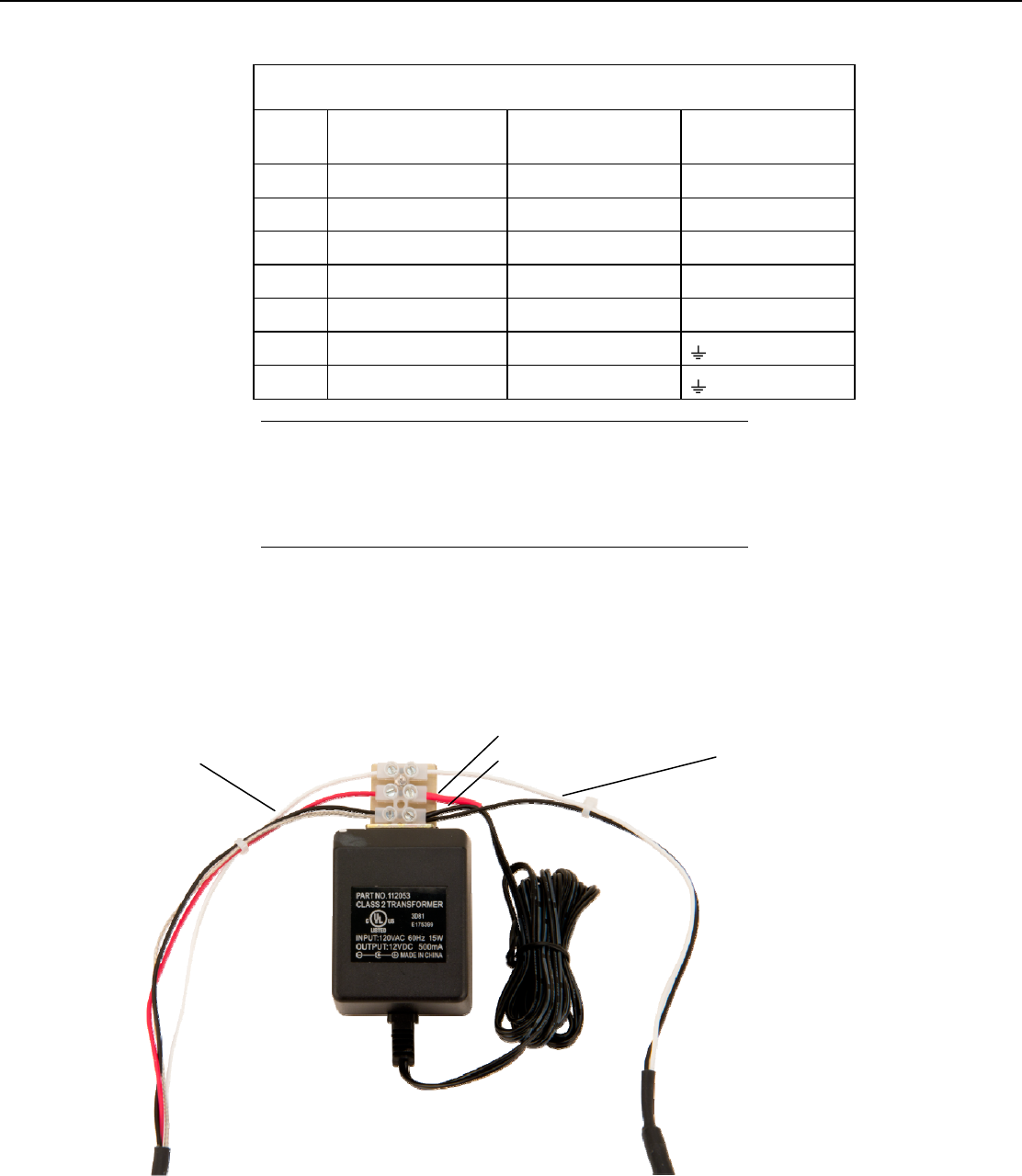
FIGURE 4-2. 43502 Aspirated Shield wiring
Transformer Connections:
Red – 12V
Black – Ground
User-Provided
Cable to Datalogger
Datalogger Connections:
White – Pulse Input
Black – Ground
Cable to 43502 Shield
(Refer to FIGURE B-2
for shield connections.)
8