
Owner's manual

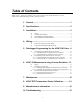
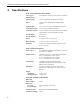
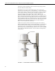
Table Of Contents
- Revision and Copyright Information
- Warranty
- Assistance
- Table of Contents
- 1. General
- 2. Specifications
- 3. Installation
- 4. Wiring
- 5. Datalogger Programming for the 43347-VX Probe
- 6. 43347-IX Measurement using Current Excitation
- 7. Maintenance
- 8. 43347 RTD Temperature Probe Calibration
- 9. Manufacturer’s Information
- 10. Troubleshooting
- 11. References
- Appendix A. Example CR10(X) Program for Ice Bath Calibration
- Appendix B. 43502 Aspirated Radiation Shield
- Appendix C. 43347 Aspirated Radiation Shield
- Appendix D. Measure Two 43347-IX Probes Using One Current Excitation Channel
- Campbell Scientific Companies
43347 RTD Temperature Probe, 43502 and 41003-5 Radiation Shields
junction box provides terminals for cable connections and properly positions
the sensor within the shield assembly.
With the blower cover open connect blower power (12 to 14 Vdc) to the
terminals on the underside of the cover (FIGURE B-2). Terminal designations
positive (POS), negative (NEG), and optional tachometer (TACH), are marked
on the printed circuit board. Blower power is normally provided by the 115
Vac to 12 Vdc plug-in power supply adapter included. BE SURE TO
OBSERVE CORRECT POLARITY. Red is positive, black is negative. The
blower motor draws approximately 420 mA to 480 mA. Use sufficiently heavy
gauge wire between the power supply adapter and the blower motor terminals
to avoid significant voltage drop. Clamp the blower power cable with the cable
clamp provided at the edge of the printed circuit card. When tying the cable to
the mounting structure provide a sufficient loop in the cable to allow the
blower cover to be opened and closed easily.
Install the 43347 probe inside the 43502 shield using the sensor mounting
bushing (supplied with the 43502) as shown in FIGURE B-1. The sensor cable
exits the side of the blower housing at the notches provided using the black
grommet to provide a seal (FIGURE B-2). Clamp the cable to the lower flange
of the housing to keep it in proper position when the cover is closed. Route the
sensor cable to the instrument enclosure. Secure the cable to the tripod/tower
using cable ties.
FIGURE 3-1. 43502 Radiation Shield mounted to tripod mast
43502 Shield
4