
User Manual


Model 083E Relative Humidity and Temperature Sensor
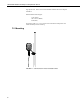
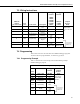
7.3 Wiring Instructions
083E Pin
Number
(pin F not used)
Wire
Color Cable Label Description
Datalogger
Channel
CR800
CR850
CR5000
CR3000
CR1000
CR23X
Datalogger
Channel
CR10(X)
CR500
CR510
Jumped
Resistor
28430
A White Power 12V
+10 to +18
Vdc
12V 12V
B Green Ground Signal Ground G G
C Blue Signal ref
RH Analog
Output
SE SE
D Black
Signal reference
temperature
Temperature
Common
AG
E Red Signal temp
Temperature
Signal
SE SE
Clear Shield Shield
G
EX or VX EX or VX
Jump resistor
between SE and
VX
7.4 Programming
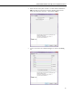
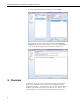
This section is for users who write their own CRBasic datalogger programs.
To use the Short Cut program builder, see Section 4, Quickstart.
7.4.1 Programming Example
Table 7-1 describes the sensor wiring used with the following example
CRBasic datalogger program.
TABLE 7-1. 083E Sensor Wiring for Example Program
Wire
Color
Cable Label
Datalogger
Channel
CR1000
Jumped
Resistor
28430
White Power 12V 12V
Green Ground G
Blue Signal ref SE1
Black
Signal reference
temperature
Red Signal temp SE8
Clear Shield
VX1
Jump resistor
between SE8
and VX1
9