Model 024A Met One Wind Direction Sensor Revision: 10/12 C o p y r i g h t © 1 9 8 9 - 2 0 1 2 C a m p b e l l S c i e n t i f i c , I n c .
Warranty “PRODUCTS MANUFACTURED BY CAMPBELL SCIENTIFIC, INC. are warranted by Campbell Scientific, Inc. (“Campbell”) to be free from defects in materials and workmanship under normal use and service for twelve (12) months from date of shipment unless otherwise specified in the corresponding Campbell pricelist or product manual. Products not manufactured, but that are re-sold by Campbell, are warranted only to the limits extended by the original manufacturer.
Assistance Products may not be returned without prior authorization. The following contact information is for US and international customers residing in countries served by Campbell Scientific, Inc. directly. Affiliate companies handle repairs for customers within their territories. Please visit www.campbellsci.com to determine which Campbell Scientific company serves your country. To obtain a Returned Materials Authorization (RMA), contact CAMPBELL SCIENTIFIC, INC., phone (435) 227-9000.
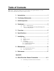
Table of Contents PDF viewers: These page numbers refer to the printed version of this document. Use the PDF reader bookmarks tab for links to specific sections. 1. Introduction .................................................................1 2. Cautionary Statements...............................................1 3. Initial Inspection .........................................................1 4. Quickstart ....................................................................2 4.1 4.
Table of Contents Figures 4-1. 4-2. 7-1. 7-2. 7-3. 8-1. 8-2. A-1. A-2. A-3. Bushing installation on 024A sensor ................................................... 2 The 024A mounted to a crossarm via the 17953 NU-RAIL................ 3 CM220 mount attached to a crossarm ................................................. 8 CM216 mount...................................................................................... 8 Schematic of 024A Wind Direction Sensor.........................................
024A Met-One Wind Direction Sensor 1. Introduction The 024A is a wind vane manufactured by Met One. It measures wind direction only and is traditionally used in tandem with Met One’s 014A Wind Speed Sensor. Before installing the 024A, please study • • • 2. 3. Section 2, Cautionary Statements Section 3, Initial Inspection Section 4, Quickstart Cautionary Statements • The 024A is a precision instrument. Please handle it with care.
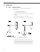
024A Met-One Wind Direction Sensor 4. Quickstart 4.1 Step 1 — Mount the Sensor Please review Section 7, Installation, for siting and other guidelines. Install the 024A using: • • CM220 Right-Angle Mounting Kit, or 17953 1 x 1 inch NURAIL Crossover Fitting 1. Remove the Allen hex screw in the lower part of the sensor housing (see FIGURE 4-1). 2. Insert the 024A in the mounting bushing (see FIGURE 4-1). 3. Tighten the screw in the bushing onto the sensor housing (see FIGURE 4-1). FIGURE 4-1.
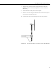
024A Met-One Wind Direction Sensor 7. Align the sensor so that the counter weight points to True South and tighten the U-bolts on the CM220 or tighten the set screws on the NURAIL fitting. 8. Connect the cable assembly to the sensor receptacle. 9. Route the sensor cable along the underside of the crossarm to the tripod or tower, and to the instrument enclosure. 10. Secure the cable to the crossarm and tripod or tower using cable ties. FIGURE 4-2.
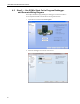
024A Met-One Wind Direction Sensor 4.2 Step 2 — Use SCWin Short Cut to Program Datalogger and Generate Wiring Diagram The simplest method for programming the datalogger to measure the 024A is to use Campbell Scientific's SCWin Short Cut Program Generator. 4 1. Open Short Cut and click on New Program. 2. Select the datalogger and enter the scan interval.
024A Met-One Wind Direction Sensor 3. Select 024A Wind Direction Sensor and select the right arrow to add it to the list of sensors to be measured then select next. 4.
024A Met-One Wind Direction Sensor 5. 5. Wire according to the wiring diagram generated by SCWin Short Cut. Overview Met One's 024A is a wind vane that measures wind direction from 0 to 360 degrees with a 5 degree accuracy. It uses a 10-kohm potentiometer to sense wind direction. A datalogger applies a precision excitation voltage to the potentiometer, resulting in an analog voltage output that is directly proportional to the wind direction's azimuth.
024A Met-One Wind Direction Sensor 6. 7. Specifications Compatible Dataloggers: CR200(X) CR800 series CR1000 CR3000 CR5000 CR9000(X) CR510 CR10(X) CR23X CR7 21X Range: 0 to 360 degrees Threshold: 0.447 m s-1 (1.0 mph) Accuracy: ±5 degrees Temperature Range: -50° to +70°C Delay Distance: Less than 1.5 m (5 ft.) Damping Ratio Standard: Optional: 0.25 0.
024A Met-One Wind Direction Sensor 7.2 Mounting Options The 024A can be attached to a CM202, CM204, or CM206 crossarm via a 17953 NU-RAIL fitting (see FIGURE 4-2 in Quickstart) or a CM220 Right Angle Mounting Bracket (see FIGURE 7-1). Alternatively, the 024A can be attached to the top of our stainless-steel tripods via the CM216 Sensor Mounting Kit (see FIGURE 7-2). The CM216 extends 4 in. above the mast of a stainless-steel CM110, CM115, or CM120 tripod. FIGURE 7-1.
024A Met-One Wind Direction Sensor 7.3 Wiring FIGURE 7-3. Schematic of 024A Wind Direction Sensor FIGURE 7-3 and TABLE 7-1 shows wiring; a detailed cable diagram is provided in Section 8, Maintenance (FIGURE 8-1). When Short Cut is used to create the datalogger program, the sensor should be wired to the channels shown on the wiring diagram created by Short Cut. TABLE 7-1. Connections to Campbell Scientific Dataloggers 7.4 Color Description CR800 CR5000 CR3000 CR1000 Red Wind Dir.
024A Met-One Wind Direction Sensor codes, and delays for CSI dataloggers are listed in TABLE 7-2. The process for determining the correct multiplier is provided in Section 7.4.2, Calibration and Orientation. TABLE 7-2.
024A Met-One Wind Direction Sensor 7.4.3 Example Programs NOTE For these examples, the multiplier is listed as 1. The multiplier is unique to individual devices. Follow the procedure provided in Section 7.4.2, Calibration and Orientation, to acquire the correct multiplier for your sensor. 'CR200(X) Series 'Created by Short Cut (2.
024A Met-One Wind Direction Sensor 'Main Program BeginProg Scan(5,Sec,1,0) 'Default Datalogger Battery Voltage measurement Batt_Volt: Battery(Batt_Volt) '024A Wind Direction Sensor measurement WindDir: BrHalf(WindDir,1,mV2500,1,1,1,2500,True,2000,250,1.0,0) NewMult=360/WindDir 'Call Data Tables and Store Data CallTable(Table1) CallTable(Table2) NextScan EndProg 'CR3000 'Created by Short Cut (2.
024A Met-One Wind Direction Sensor ;{CR10X} ; *Table 1 Program 01: 10 Execution Interval (seconds) ;Measure sensor. Multiplier is unique to individual devices. 1: Excite-Delay (SE) (P4) 1: 1 Reps 2: 14 250 mV Fast Range 3: 1 SE Channel 4: 1 Excite all reps w/Exchan 1 5: 2 Delay (0.01 sec units) 6: 500 mV Excitation 7: 1 Loc [ wind_dir ] 8: 1.0 Multiplier 9: 0.
024A Met-One Wind Direction Sensor FIGURE 8-1.
024A Met-One Wind Direction Sensor FIGURE 8-2.
024A Met-One Wind Direction Sensor TABLE 8-1. Met-One Parts List Reproduced by Campbell Scientific, Inc. Item Part No. Description. Qty./Assy 1 102105 Vane Assembly 1 2 101685-1 Wind Dir. Support 1 3 101049-2 Label, Wind Dir.
024A Met-One Wind Direction Sensor 9. References The following references give detailed information on siting wind speed and wind direction sensors. EPA, 1989: Quality Assurance Handbook for Air Pollution Measurements System, Office of Research and Development, Research Triangle Park, NC, 27711. EPA, 1987: On-Site Meteorological Program Guidance for Regulatory Modeling Applications, EPA-450/4-87-013, Office of Air Quality Planning and Standards, Research Triangle Park, NC 27711.
024A Met-One Wind Direction Sensor 18
Appendix A. Wind Direction Sensor Orientation A.1 Determining True North and Sensor Orientation Orientation of the wind direction sensor is done after the datalogger has been programmed, and the location of True North has been determined. True North is usually found by reading a magnetic compass and applying the correction for magnetic declination; where magnetic declination is the number of degrees between True North and Magnetic North.
Appendix A. Wind Direction Sensor Orientation FIGURE A-1.
Appendix A. Wind Direction Sensor Orientation FIGURE A-2. Declination angles east of True North are subtracted from 0 to get True North FIGURE A-3.
Appendix A.
Campbell Scientific Companies Campbell Scientific, Inc. (CSI) 815 West 1800 North Logan, Utah 84321 UNITED STATES www.campbellsci.com • info@campbellsci.com Campbell Scientific Africa Pty. Ltd. (CSAf) PO Box 2450 Somerset West 7129 SOUTH AFRICA www.csafrica.co.za • cleroux@csafrica.co.za Campbell Scientific Australia Pty. Ltd. (CSA) PO Box 8108 Garbutt Post Shop QLD 4814 AUSTRALIA www.campbellsci.com.au • info@campbellsci.com.au Campbell Scientific do Brazil Ltda.