INSTRUCTION MANUAL Model 014A Met One Wind Speed Sensor Revision: 4/14 C o p y r i g h t © 1 9 8 0 - 2 0 1 4 C a m p b e l l S c i e n t i f i c , I n c .
Limited Warranty “Products manufactured by CSI are warranted by CSI to be free from defects in materials and workmanship under normal use and service for twelve months from the date of shipment unless otherwise specified in the corresponding product manual. (Product manuals are available for review online at www.campbellsci.com.) Products not manufactured by CSI, but that are resold by CSI, are warranted only to the limits extended by the original manufacturer.
Assistance Products may not be returned without prior authorization. The following contact information is for US and international customers residing in countries served by Campbell Scientific, Inc. directly. Affiliate companies handle repairs for customers within their territories. Please visit www.campbellsci.com to determine which Campbell Scientific company serves your country. To obtain a Returned Materials Authorization (RMA), contact CAMPBELL SCIENTIFIC, INC., phone (435) 227-9000.
Precautions DANGER — MANY HAZARDS ARE ASSOCIATED WITH INSTALLING, USING, MAINTAINING, AND WORKING ON OR AROUND TRIPODS, TOWERS, AND ANY ATTACHMENTS TO TRIPODS AND TOWERS SUCH AS SENSORS, CROSSARMS, ENCLOSURES, ANTENNAS, ETC. FAILURE TO PROPERLY AND COMPLETELY ASSEMBLE, INSTALL, OPERATE, USE, AND MAINTAIN TRIPODS, TOWERS, AND ATTACHMENTS, AND FAILURE TO HEED WARNINGS, INCREASES THE RISK OF DEATH, ACCIDENT, SERIOUS INJURY, PROPERTY DAMAGE, AND PRODUCT FAILURE.
Table of Contents PDF viewers: These page numbers refer to the printed version of this document. Use the PDF reader bookmarks tab for links to specific sections. 1. Introduction ................................................................. 1 2. Cautionary Statements ............................................... 1 3. Initial Inspection ......................................................... 1 3.1 Ships With ............................................................................................
Table of Contents A.1.2 Edlog Dataloggers .................................................................... A-2 B. Example Programs.................................................. B-1 B.1 Pulse Port Examples ........................................................................ B-1 B.1.1 CR1000 Example Program ....................................................... B-1 B.1.2 CR10X Example Program ........................................................ B-2 B.2 Control Port Example Program .........
Met One 014A Wind Speed Sensor 1. Introduction The 014A is a three-cup anemometer that monitors horizontal wind speed for the range of 0 to 45 m s–1 with a threshold of 0.45 m s–1. It connects directly to a Campbell Scientific datalogger, which measures the 014A’s pulse signal and converts the signal to engineering units (mph, m s–1, knots).
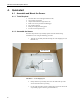
Met One 014A Wind Speed Sensor 4. Quickstart 4.1 Assemble and Mount the Sensor 4.1.1 Tools Required • • • • • • • 5/64 inch Allen wrench (shipped with the 014A) 1/2 inch open end wrench compass and declination angle for the site small screw driver provided with datalogger UV resistant cable ties small pair of diagonal-cutting pliers 6 inch to 10 inch torpedo level 4.1.2 Assemble the Sensor The 014A ships with the cup assembly separate from the main housing.
Met One 014A Wind Speed Sensor Allen Wrench FIGURE 4-2. Allen wrench tightening bolt 4. Ensure that the cup assembly spins freely. 4.1.3 Mount to a Tripod or Tower This quickstart installs the 014A using: • • 1049 3/4 x 1 inch NU-RAIL® Crossover Fitting (FIGURE 4-3), or CM220 Right-Angle Mounting Kit (FIGURE 4-4) Please review Section 7, Installation, for siting and other guidelines. 1. Mount a CM200-series crossarm to the tripod or tower. 2.
Met One 014A Wind Speed Sensor 5. Route the sensor cable along the underside of the crossarm to the tripod/tower, and to the instrument enclosure. 6. Secure the cable to the crossarm and tripod/tower using cable ties. Crossarm Sensor Base 1049 NU-RAIL FIGURE 4-3. 014A mounted on a crossarm with pn 1049 U-bolt holds sensor base Crossarm CM220 Mounting Bracket FIGURE 4-4.
Met One 014A Wind Speed Sensor 4.2 Use SCWin to Program Datalogger and Generate Wiring Diagram Short Cut is an easy way to program your datalogger to measure the 014A and assign datalogger wiring terminals. The following procedure shows using Short Cut to program the 014A. 1. Install Short Cut by clicking on the install file icon. Get the install file from either www.campbellsci.com, the ResourceDVD, or find it in installations of LoggerNet, PC200W, PC400, or RTDAQ software. 2.
Met One 014A Wind Speed Sensor 4. Select Datalogger Model and Scan Interval (default of 5 seconds is OK for most applications). Click Next. 5. Under the Available Sensors and Devices list, select the Sensors | Meteorological | Wind Speed & Direction folder. Select 014A Wind Speed Sensor. Click to move the selection to the Selected device window. The wind speed defaults to meters/second. This can be changed by clicking the Wind Speed box and selecting one of the other options.
Met One 014A Wind Speed Sensor 5. 6. After selecting the sensor, click at the left of the screen on Wiring Diagram to see how the sensor is to be wired to the datalogger. The wiring diagram can be printed out now or after more sensors are added. 7. Select any other sensors you have, then finish the remaining Short Cut steps to complete the program. The remaining steps are outlined in Short Cut Help, which is accessed by clicking on Help | Contents | Programming Steps. 8.
Met One 014A Wind Speed Sensor TABLE 5-1. Recommended Lead Lengths CM106 CM110 CM115 CM120 UT10 UT20 UT30 14 ft 14 ft 19 ft 24 ft 14 ft 24 ft 37 ft The 014A’s cables can terminate in: 6. • Pigtails that connect directly to a Campbell Scientific datalogger (cable termination option –PT). • Connector that attaches to a prewired enclosure (cable termination option –PW).
Met One 014A Wind Speed Sensor 7. Installation If you are programming your datalogger with Short Cut, skip Section 7.3, Wiring, and Section 7.4, Programming. Short Cut does this work for you. See Section 4, Quickstart, for a Short Cut tutorial. 7.1 Siting Locate wind sensors away from obstructions (for example, trees and buildings). As a general rule, there should be a horizontal distance of at least ten times the height of the obstruction between the sensor and the obstruction.
Met One 014A Wind Speed Sensor 7.3 Wiring The 014A is typically connected to a datalogger’s pulse port (see TABLE 7-1). TABLE 7-1. Connections to Campbell Scientific Dataloggers Pulse Channels Color Wire Label CR800 CR850 CR5000 CR3000 CR1000 CR9000X Black Signal Pulse White Signal Reference G Clear Shield G CR510 CR500 CR10(X) 21X CR7 CR23X CR200(X) Pulse Pulse P_SW A control port may also be used to measure the 014A. With this option, the white wire is connected to the 5 V terminal.
Met One 014A Wind Speed Sensor NOTE Short Cut cannot edit programs after they are imported and edited in CRBasic Editor. A Short Cut tutorial is available in Section 4.2, Use SCWin to Program Datalogger and Generate Wiring Diagram. If you wish to import Short Cut code into either CRBasic Editor or Edlog to create or add to a customized program, follow the procedure in Appendix A.1, Importing Short Cut Code into a Program Editor.
Met One 014A Wind Speed Sensor 8.1.2 12 to 24 Month Service Replace sensor bearings. 8.1.3 24 to 36 Month Service A complete factory overhaul of the sensor is recommended. Contact Met One directly for wind speed sensor repair and recalibration service. This repair and calibration service includes disassembly and detailed inspection of all moving mechanical parts and all electronic components. Service includes replacement of bearings, shaft, and set screws as well as a functional test of the sensor.
Met One 014A Wind Speed Sensor The State Climatologist, 1985: Publication of the American Association of State Climatologists: Height and Exposure Standards, for Sensors on Automated Weather Stations, vol. 9, No. 4. WMO, 1983: Guide to Meteorological Instruments and Methods of Observation, World Meteorological Organization, No. 8, 5th edition, Geneva, Switzerland.
Met One 014A Wind Speed Sensor 14
Appendix A. Importing Short Cut Code This tutorial shows: • • How to import a Short Cut program into a program editor for additional refinement. How to import a wiring diagram from Short Cut into the comments of a custom program. A.1 Importing Short Cut Code into a Program Editor Short Cut creates files that can be imported into either CRBasic Editor or Edlog program editor. These files normally reside in the C:\campbellsci\SCWin folder and have the following extensions: • • • • • • • • .
Appendix A. Importing Short Cut Code 5. The program can now be edited, saved, and sent to the datalogger. 6. Import wiring information to the program by opening the associated .DEF file. Copy and paste the section beginning with heading “-Wiring for CRXXX–” into the CRBasic program, usually at the head of the file. After pasting, edit the information such that a ' character (single quotation mark) begins each line.
Appendix B. Example Programs B.1 Pulse Port Examples The following CR1000 and CR10X programs use a pulse port to measure the 014A every 5 seconds. The programs store mean wind speed (in m s–1) every 60 minutes. Wiring for the examples is given in TABLE B-1. TABLE B-1. Wiring for Pulse Port Example Programs Color Description CR1000 CR10X Black Signal P1 P1 White Signal Reference G Clear Shield G B.1.
Appendix B. Example Programs B.1.2 CR10X Example Program ;{CR10X} *Table 1 Program 01: 5.0000 Execution Interval (seconds) 1: Batt Voltage (P10) 1: 1 Loc [ Batt_Volt ] 2: Pulse (P3) 1: 1 2: 1 3: 22 4: 2 5: 0.8 6: 0.447 3: If 1: 2: 3: 4: Reps Pulse Channel 1 Switch Closure, Output Hz Loc [ WS_ms ] Multiplier Offset (X<=>F) (P89) 2 X Loc [ WS_ms 4 < 0.
Appendix B. Example Programs B.2 Control Port Example Program The following CR5000 program uses control ports to measure three 014A wind speed sensor. The program measures them every second and stores the mean wind speed (in m s–1) every 15 seconds.
Appendix B.
Appendix C. Sensor Maintenance C.1 Reed Switch Replacement Procedure To verify parts and locations, refer to the cable and parts diagrams (FIGURE C-2 and FIGURE C-3) and the parts list (TABLE C-1). A. Remove sensor from mounting arm and disconnect cable. B. Remove the cup assembly. C. Remove the three Philips screws at the top of the sensor and lift out the bearing mount assembly. D. Unsolder the leads of the reed switch and remove the switch from the two mounting terminals, see the parts diagram.
Appendix C. Sensor Maintenance C. Insert a right-angle type of tool, such as an Allen wrench, into bearing. Cock it slightly to one side and remove both bearings. D. Install new bearings. Be careful not to introduce dirt particles into bearings. CLEAN HANDS ONLY! DO NOT ADD LUBRICATION OF ANY KIND. E. Reassemble the sensor in reverse order. Be sure to include spacers over the bearings when replacing the shaft in the bearing mount.
Appendix C. Sensor Maintenance FIGURE C-3.
Appendix C. Sensor Maintenance TABLE C-1. Met One Parts List Reproduced by Campbell Scientific, Inc. C-4 Item Part No. Description Qty.
Appendix D. Theory of Operation D.1 Mechanical The sensor’s cup assembly consists of three aluminum cups mounted on a cup assembly hub. A stainless steel shaft, which rotates on precision-sealed ball bearings, connects the cup assembly to a magnet assembly. When the shaft is rotated, the turning magnet assembly causes a reed switch to close. There are two contacts (reed switch closures) per revolution. The frequency of closures is linear from threshold to 45 m s–1. D.
Appendix D.
Campbell Scientific Companies Campbell Scientific, Inc. (CSI) 815 West 1800 North Logan, Utah 84321 UNITED STATES www.campbellsci.com • info@campbellsci.com Campbell Scientific Centro Caribe S.A. (CSCC) 300 N Cementerio, Edificio Breller Santo Domingo, Heredia 40305 COSTA RICA www.campbellsci.cc • info@campbellsci.cc Campbell Scientific Africa Pty. Ltd. (CSAf) PO Box 2450 Somerset West 7129 SOUTH AFRICA www.csafrica.co.za • cleroux@csafrica.co.za Campbell Scientific Ltd.