
Measurement and Control Module Operators Manual

SECTION 7. MEASUREMENT PROGRAMMING EXAMPLES
7-6
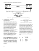
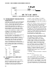
FIGURE 7.8-1. Wiring Diagram for Rain Gage with Long Leads
7.8 TIPPING BUCKET RAIN GAGE WITH
LONG LEADS
A tipping bucket rain gage is measured with the
Pulse Count Instruction configured for Switch
Closure. Counts from long intervals will be
used, as the final output desired is total rainfall
(obtained with Instruction 72, Totalize). If
counts from long intervals were discarded, less
rainfall would be recorded than was actually
measured by the gage (assuming there were
counts in the long intervals). Output is desired
in millimeters of precipitation. The gage is
calibrated for a 0.01 inch tip, therefore, a
multiplier of 0.254 is used.
In a long cable there is appreciable capacitance
between the lines. The capacitance is
discharged across the switch when it closes. In
addition to shortening switch life, a transient
may be induced in other wires packaged with
the rain gage leads each time the switch
closes. The 100 ohm resistor protects the
switch from arcing and the associated transient
from occurring, and should be included any
time leads longer than 100 feet are used with a
swit
ch closure.
PROGRAM
01: P3 Pulse
01: 1 Rep
02: 1 Pulse Input Chan
03: 2 Switch closure
04: 11 Loc [:RAIN mm ]
05: 0.254 Mult
06: 0 Offset
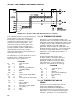
7.9 100 OHM PRT IN 4 WIRE HALF
BRIDGE
Instruction 9 is the best choice for accuracy
where the Platinum Resistance Thermometer
(PRT) is separated from other bridge
completion resistors by a lead length having
more than a few thousandths of an ohm
resistance. In this example, it is desired to
measure a temperature in the range of -10 to
40°C. The length of the cable from the CR10 to
the PRT is 500 feet.
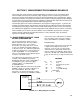
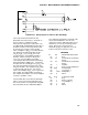
Figure 7.9-1 shows the circuit used to measure
the PRT. The 10 kohm resistor allows the use
of a high excitation voltage and low voltage
ranges on the measurements. This insures that
noise in the excitation does not have an effect
on signal noise. Because the fixed resistor (R
f
)
and the PRT (R
s
) have approximately the same
resistance, the differential measurement of the
voltage drop across the PRT can be made on
the same range as the differential
measurement of the voltage drop across R
f
.
If the voltage drop across the PRT (V
2
) is kept
under 50mV, self heating of the PRT should be
less than 0.001°C in still air. The best
resolution is obtained when the excitation
voltage is large enough to cause the signal
voltage to fill the measurement voltage range.
The resolution of this measurement on the
25mV range is +0.04°C. The voltage drop
across the PRT is equal to V
x
multiplied by the
ratio of R
s
to the total resistance, and is
greatest when R
s
is greatest (R
s
=115.54 ohms
at 40°C). To find the maximum excitation
voltage that can be used, we assume V
2
equal
to 25 mV and use Ohm's Law to solve for the
resulting current, I.
I = 25mV/R
s
= 25mV/115.54 ohms = 0.216 mA
Next solve for V
x
:
V
x
= I(R
1
+R
s
+R
f
) = 2.21V
If the actual resistances were the nominal
values, the CR10 would not over range with V
x
= 2.2 V. To allow for the tolerances in the
actual resistances, it is decided to set V
x
equal
to 2.1 volts (e.g., if the 10 kohms resistor is 5%
low, then R
s
/(R
1
+R
s
+R
f
)=115.54/9715.54, and
V
x
must be 2.102V to keep V
s
less than 25mV).