
Measurement and Control Module Operators Manual


SECTION 4. EXTERNAL STORAGE PERIPHERALS
4-5
4.3.3 TAPE FORMAT
Data is transferred to cassette tape in the high
speed/high density Format 2. Data tapes
generated by the CR10 are read by the PC201
tape read card for the IBM PC or by the C20
Cassette Interface. The C20 decodes the tape
and transmits the data in ASCII to any external
device equipped with a standard RS232
interface.
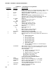
TABLE 4.3-2. Format 2 Specifications
Data Binary
Low Resolution 2 bytes/data point
High Resolution 4 bytes/data point
C-60 Capacity 180,000 data points
(Lo Res.)
(1 side only)
Data Transfer 100 data points/sec.
Rate (Lo Res.)
Block Size 512 Final Storage
locations
4.3.4 CONNECTING TAPE TO CR10
The procedure for setting up the CR10 and
cassette recorder for transfer to tape is as
follows:
1. Load a cassette in the recorder and
advance the tape forward until the tape
leader is past the recording head. (Internal
batteries or AC power required.)
2. Connect the SC92A or SC93A to the 9-pin
D-TYPE connector in the upper right-hand
corner of the wiring panel. (Via the SC12
ribbon cable if using *8 with CR10KD or
modem/terminal.)
3. Connect the plugs on the free end of the
SC92A or SC93A into the DC-IN and MIC
(and Ear if SC93A) jacks on the recorder.
4. Simultaneously press the RECORD and
PLAY buttons on the recorder to set it for
recording. With the DC-IN Jack plugged in,
the tape will not move until the dump occurs.
5. To test connections manually initiate
transfer by Keying in the *8 commands as
listed in Table 4.2-1. The tape should
advance as data is transferred. If the Start
of dump location is equal to the End of
dump location, the CR10 will write a
"dummy" block of data to tape.
If you are leaving the recorder with the CR10 (on-
line output to tape enabled with Instruction 96) it is
a good idea to write a dummy block of data to tape
(5 above) to ensure that the recorder is correctly
connected. Leave the CR10 in the *0 Mode.
When on-line, the CR10 dumps data to tape in 512
locat
ion blocks (unless the option to dump any new
data is selected in Instruction 96). When picking up
a data tape from a field site, dump the residual data
(data which has accumulated since the last full
block) before removing the tape. Dump the
residual data by entering the *8 Mode, advancing
through windows 2 and 3 and initiating a dump.
(The start and stop locations should be less than
512 locations apart.) After removing the old tape,
insert a new tape and go through the set up steps
above.
4.4 PRINTER OUTPUT FORMATS
Printer output can be sent in Final Storage Format
(Appendix C.2), Printable ASCII, or Comma
Delineated ASCII. These ASCII formats may also
be used when data from the Storage Modules or
Telecommunications are stored on disk with
Campbell Scientific's PC208 software.
4.4.1 PRINTABLE ASCII FORMAT
In the Printable ASCII format each data point is
preceded by a 2 digit data point ID and a (+) or
(−) sign. The ID and fixed spacing of the data
points make particular points easy to find on a
printed output. This format requires 10 bytes
per data point to store on disk.
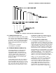
Figure 4.4-1 shows both high and low resolution
data points in a 12 data point Output Array. The
example data contains Day, Hour-Minute, and
Seconds in the 2nd - 4th data points. REMEMBER!
You must specifically program the CR10 to output
the date and time values. The Output Array ID,
Day, and Time are always 4 character numbers,
even when high resolution output is specified. The
Seconds resolution is .125 seconds.
Each full line of data contains 8 data points (79
characters including spaces), plus a carriage
return (CR) and line feed (LF). If the last data
point in a full line is high resolution, it is
followed immediately with a CR and LF. If it is
low resolution, the line is terminated with a
space, CR and LF. Lines of data containing
less than 8 data points are terminated similarly
after the last data point.