
Measurement and Control Module Operators Manual


APPENDIX C. BINARY TELECOMMUNICATIONS
C-4
Representing the bits in the first byte of each
two byte pair as ABCD EFGH (A is the most
significant bit, MSB), the byte pairs are
described here.
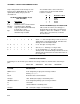
LO RESOLUTION FORMAT - D,E,F,
NOT ALL ONES
Bits Description
A Polarity, 0 = +, 1 = -.
B, C Decimal locators as defined below.
D-H plus 13 bit binary value (D=MSB).
second Largest possible number without D,
E, and F all 1 is 7167,
byte but CSI defines the largest
allowable range as 6999.
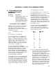
The decimal locators can be viewed as a
negative base 10 exponent with decimal
loc
ations as follows:
BC Decimal Location
0 0 XXXX.
0 1 XXX.X
1 0 XX.XX
1 1 X.XXX
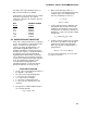
DATA TYPE WHEN D,E,F, ALL EQUAL ONE
If D, E, and F are all ones, the data type is
determined by the other bits as shown below.
X implies a "don't care" condition; i.e., the bit
can be either 1 or 0 and is not used in the
decode decision.
ABCDEFGH DATA TYPE AND SECOND BYTE FORMAT
111111XX A,B,C, = 1 - Start of Output Array, G & H are the most
significant bits of the Output Array ID. All 8 bits of the
2nd byte are also included in the ID.
XX0111XX C = 0 - First byte of a 4 byte value.
001111XX A,B = 0; C = 1 - Third byte of a 4 byte value.
01111111 A = 0; remaining bits = 1 - First byte of a 2 byte
"dummy" word. The CR10 always transmits a 0 for the
2nd byte, but the word can be decoded on the basis of
the 1st byte only.
HI RESOLUTION FORMAT
Continuing to use the A-H bit representation, the four byte number is shown below as two two byte
pairs.
AB0111GH XXXXXXXX 001111GH XXXXXXXX
BITS, 1ST BYTE,
1ST PAIR DESCRIPTION
CDEF = 0111 Code designating 1st byte pair of four byte number.
B Polarity , 0 = +, 1 = -.
G,H,A, Decimal locator as defined below.
2nd byte 16th - 9th bit (left to right) of 17 bit binary value.
ABCDEF = 001111 Code designating 2nd byte pair of four byte number.
G Unused bit.
H 17th and MSB of 17 bit binary value.
2nd byte 8th - 1st bit (left to right) of 17 bit binary value.