
Measurement and Control Module Operators Manual

SECTION 13. CR10 MEASUREMENTS
13-7
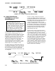
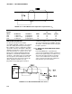
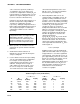
FIGURE 13.3-6. Resistive Half Bridge Connected to Single-Ended CR10 Input
R
o
, the source resistance, is not constant
because R
b
varies from 0 to 10 kohms over the
0 to 360 degree wind direction range. The
source resistance is given by:
R
o
= R
d
+(R
b
(R
s
-R
b
+R
f
)/(R
s
+R
f
)) =
R
d
+(R
b
(20k-R
b
)/20k) [13.3-12]
Note that at 360 degrees, R
o
is at a maximum
of 6k (R
b
=10k) and at 0 degrees, R
o
is 1k
(R
b
=0). It follows that settling errors are less at
lower direction values.
The value of R
b
for any direction D (degrees) is
given by:
R
b
(kohms) = (10k)(D)/360 [13.3-13]
Equation 13.3-6 can be rewritten to yield the
settling error of a rising signal directly in units of
degrees.
Error (degrees) = De
-t/(R
o(Cf+CwL))
[13.3-14]
Equation 13.3-12, -13 and -14 can be combined
to estimate the error directly in degrees at
various directions and lead lengths (Table 13.3-
3). Constants used in the calculations are
given below:
C
f
= 3.3nfd
C
w
= 41 pfd/ft., Belden #8771 wire
t = 450µs
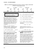
TABLE 13.3-3. Settling Error, in Degrees,
for 024A Wind Direction Sensor vs. Lead
Length
Wind Error
Direction L=1000 ft. L=500 ft.
360° 66° 15°
270° 45° 9°
180° 21° 3°
90° 4° 0°
The values in Table 13.3-3 show that significant
error occurs at large direction values for leads
in excess of 500 feet. Instruction 4, Excite,
Delay, and Measure, should be used to
eliminate errors in these types of situations.
Using a 10 ms delay, settling errors are
eliminated up to lengths that exceed the drive
capability of the excitation channel (~ 2000 ft.).
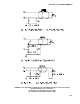
13.3.3 TRANSIENTS INDUCED BY SWITCHED
EXCITATION
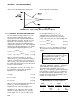
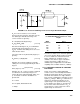
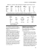
Figure 13.3-6 shows a typical half bridge
resistive sensor, such as Campbell Scientific's
Model 107 Temperature Probe, connected to
the CR10. The lead wire is a single-shielded
pair, used for conducting the excitation (V
x
) and
signal (V
s
) voltages. When V
x
is switched on, a
transient is capacitively induced in V
s
, the
signal voltage. If the peak transient level, V
eo
,
is less than the true signal, V
so
, the transient
has no effect on the measurement. If V
eo
is
greater than V
so, it must settle to the correct
signal voltage to avoid errors.