
Measurement and Control Module Operators Manual

SECTION 9. INPUT/OUTPUT INSTRUCTIONS
9-15
PARAM. DATA
NUM. TYPE DESCRIPTION
01: 4 MASK (0-255)
02: 4 INPUT LOCATION TO
STORE RESULT
Input locations altered: 1
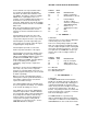
*** 26 TIMER ***
FUNCTION
This instruction will reset a timer or store the
elapsed time registered by the timer in seconds
in an Input Storage location. Instruction 26 can
be used with Program Control Instructions to
measure the elapsed time between specific
input conditions. There is only one timer and it
is
common to all tables (e.g., if the timer is reset
in Table 1 and later in Table 2, a subsequent
instruction in Table 1 to read the timer will store
the elapsed time since the timer was reset in
Table 2).
Elapsed time is tracked in 0.125 second
increments. The maximum interval that can be
timed is 8191.875 seconds.
The timer is also reset in response to certain
keyboard entries:
1. When tables are changed and compiled
with the *0 Mode, the timer is reset
automatically.
2. Entering "*6" after changing the program
compiles the programs, but does NOT
res
et the timer.
PARAM. DATA
NUM. TYPE DESCRIPTION
01: 4 Input location no. of
elapsed time in
seconds (or enter 0 to
reset)
Input locations altered: 1
(0 if timer is being reset)
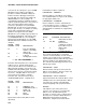
*** 27 PERIOD MEASUREMENT ***
FUNCTION
Instruction 27 measures the period
(microseconds) of a signal on a single ended
input channel. As an option, the frequency of
the signal in kHz may be output instead of the
period. The specified number of cycles are
timed with a resolution of +60 nanoseconds,
making the resolution on the period 60
nanoseconds divided by the number of cycles
measured. Resolution is reduced by noise and
signals with a slow transition through the zero
voltage threshold. The "Time out" parameter
specifies the maximum length of time the
instruction will wait on each repetition for the
specified number of cycles. If the cycles have
not been counted within this time, -99999 will
be loaded into the input location.
Input Frequency Gain Codes
Range Peak to Peak Volts Maximum
Code Required @ Max. Freq.* Frequency
12mV 8 kHz
2 3 mV 20 kHz
3 12 mV 50 kHz
4 2 V 200 kHz
0x Output period in microseconds
1x Output frequency in kHz where x is range
code
* AC voltage; must be centered around CR10 ground.
PARAM. DATA
NUM. TYPE DESCRIPTION
01: 2 Repetitions
02: 2 Gain/output option
03: 2 Single-ended input
channel
04: 4 # Cycles to measure
05: 4 Time out (0.01 sec, at
least the maximum
duration of the number
of cycles specified + 1
1/2 cycles.)
06: 4 Destination input
location
07: FP Multiplier
08: FP Offset
Input locations altered: 1* Repetitions
*** 28 VIBRATING WIRE ***
MEASUREMENT
FUNCTION
Excites a vibrating wire sensor with a swept
frequency (from low frequency to high), then
measures the response period and calculates 1/T
2
,
where T is the period in ms. Excitation is normally
provided for before each repetition. As an option, a
single excitation can be made prior to all repetitions