
Measurement and Control Module Operators Manual

SECTION 9. INPUT/OUTPUT INSTRUCTIONS
9-13
03: 2 Single-ended or
differential channel for
first analog
measurements
04: 4 Option, 4 digit code
ABCD
A Trigger
0 - Trigger on 1st
analog channel
1 - Digital trigger
on Control Port #1
2 Same as 0, but
set Digital Control
Port #1 high when
trigger is met, low
when done
measuring
B Trigger option
0 - Trigger
immediately
1 - Trigger if
above limit (high)
2 - Trigger if
below limit (low)
3 - Trigger on
rising edge
4 - Trigger on
falling edge
C Destination
0 - Input Storage
1 - Serial port
9600 baud
2 - Serial port
76,800 baud
3 - Serial port
76,800 baud to
SM192/716
D Measurement
0 - Differential
measurement
1 - Single-ended
measurement
05: FP Scan interval (ms,
minimum 1.333 x reps,
limited to 1.333-50 ms)
06: FP Number of scans (units
of 1000)
07: 4 Number of samples
saved before trigger (not
used with serial output)
08: FP Trigger limit (mV,
unscaled measurement)
09: 4 Excitation voltage (mV)
10: 4 1st input location in
which to store data
11: FP Multiplier (not used
with serial output)
12: FP Offset (not used with
serial output)
*** 24 CALIBRATION ***
FUNCTION
Put 19 calibration values into input locations. If
C (--) is keyed before entering the input
location, then the automatic calibrations are
simply displayed, not measured. Otherwise,
the calibration takes place only when
Instruction 24 is executed; automatic calibration
is disabled (Section 13.7).
PARAM. DATA
NUMBER TYPE DESCRIPTION
01: 4 Input location number,
key
C (--) for results of
automatic calibration
Input locations altered: 19
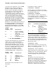
*** 25 PORT READ ***
FUNCTION
The status of a group of ports selected by a
mask is read and placed in an input location.
The status is a base 2 representation of the
ports converted to base 10. Port 1 is the least
significant bit. For example, if all ports are
read, and the port status is as follows:
PORT C8 C7 C6 C5 C4 C3 C2 C1
VALUE 128 64 32 16 8 4 2 1
STATUS 00110010
(0=low,
1=high)
Base 10 equivalent: 32 + 16 + 2 = 50
50 will be stored in the input location.
The mask is also base 2 representation; 1
indicates the port is to be read, 0 results in a 0
for the port regardless of the status of the port
(AND operation). For example, if 50 (see
above example) is entered for the mask, ports
2, 5, and 6 are read. If only ports 4 and 5 are
high, the status will be 16 (port 4 is not read).