
Measurement and Control Module Operators Manual

SECTION 9. INPUT/OUTPUT INSTRUCTIONS
9-6
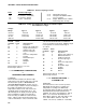
Thermistor Probe, makes a fast, single-ended
voltage measurement across a resistor in
series with the thermistor, and calculates the
temperature in °C with a polynomial. A 1
before the excitation channel number (1X)
causes the channel to be incremented with
each repetition. The maximum polynomial error
from -40°C to +56°C is given here:
Curve Fit Error --
Range (°C) Error (°C)
-40 to +56 +1.0
-24 to +48 +0.1
PARAM. DATA
NUMBER TYPE DESCRIPTION
01: 2 Repetitions
02: 2 Single-ended channel
number of first
measurement
03: 2 Excitation channel
number
04: 4 Input location for first
measurement
05: FP Multiplier
06: FP Offset
Input locations altered: 1 for each thermistor
channel
*** 12 207 RELATIVE HUMIDITY PROBE ***
FUNCTION
This instruction applies a 1.5 VAC excitation
across Campbell Scientific's Model 207
Temperature and RH Probe, makes a fast
single-ended measurement across a series
resistor, calculates the result with a 5th order
polynomial, and performs the required
temperature compensation before outputting
the result in % RH.
When measuring several probes, all the RH
elements should be connected sequentially.
The temperature values used to correct the RH
measurements should also be stored
sequentially to make use of the REP feature in
Instruction 11.
NOTE: The temperature value used in
compensating the RH value (Parameter 5)
must be obtained (see Instruction 11) prior
to executing Instruction 12 and must be in
Celsius.
The RH results are placed sequentially into the
input locations beginning with the first RH
value.
In the 207 probe, the RH and temperature
elements use a common excitation line.
CAUTION: Never excite the 207 probe
with DC excitation because the RH chip will
be damaged.
A 1 before the excitation channel number (1X)
causes the channel to be incremented with
each repetition.
The maximum RH polynomial error is given
here:
Curve Fit Error --
Range (%RH) Error (%RH)
10 - 100 +4
15 - 94 +1
PARAM. DATA
NUMBER TYPE DESCRIPTION
01: 2 Repetitions
02: 2 First single-ended
channel for RH
measurement
03: 2 Excitation channel
number
04: 4 Input location for first
compensating
temperature
measurement (°C)
05: 4 Input location for first
R.H. measurement
06: FP Multiplier
07: FP Offset
Input locations altered: 1 for each RH
measurement
*** 13 THERMOCOUPLE TEMPERATURE,
***
SINGLE-ENDED
FUNCTION
This instruction uses the selected thermocouple
calibration to calculate the thermocouple output
voltage at the reference temperature, then it
makes a SINGLE-ENDED VOLTAGE
MEASUREMENT (Section 13.2) on the
thermocouple and adds the measured voltage