
Measurement and Control Module Operators Manual


SECTION 9. INPUT/OUTPUT INSTRUCTIONS
9-5
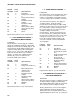
is specified, the inputs for the differential
measurement are not switched for a second
integration as is normally the case. With the 0
delay, Instruction 8 does not have as good
resolution or common mode rejection as other
differential measurements. It does provide a
very rapid means of making bridge
measurements. This instruction does not
reverse excitation. A 1 before the excitation
channel number (1X) causes the channel to be
incremented with each repetition.
PARAM. DATA
NUMBER TYPE DESCRIPTION
01: 2 Repetitions
02: 2 Range code (Table 9-1)
03: 2 Differential channel
number for first
measurement
04: 2 Excitation channel
number
05: 4 Delay (0.01s)
06: 4 Excitation voltage
(millivolts)
07: 4 Input location number
for first measurement
08: FP Multiplier
09: FP Offset
Input locations altered: 1 per measurement
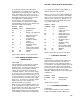
*** 9 FULL BRIDGE WITH EXCITATION ***
COMPENSATION
FUNCTION
This instruction is used to apply an excitation
voltage and make two differential voltage
measurements. The measurements are made
with both positive and negative excitation
voltage. The measurements are made on
sequential channels. The result is the voltage
measured on the second channel (V
2
) divided
by the voltage measured on the first (V
1
). If V
1
is measured on the 2.5 V range (code 5,15, 25
or 35 in Parameter 2), then the result is 1000
times V
2
/V
1
. A 1 before the excitation channel
number (1X) causes the channel to be
incremented with each repetition.
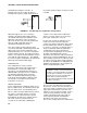
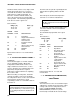
When used as a 6 wire full bridge (Figure 13.5-
1), the connections are made so that V
1
is the
measurement of the voltage drop across the full
bridge, and V
2
is the measurement of the
bridge output. Because the excitation voltage
for a full bridge measurement is usually in the
2.5 V range, the output is usually 1000 V
2
/V
1
or
millivolts output per volt excitation.
When used to measure a 4 wire half bridge, the
connections are made so that V
1
is the voltage
drop across the fixed resistor (R
f
), and V
2
is the
drop across the sensor (R
s
). As long as V
1
is
not measured on the 2.5V range, the result is
V
2
/V
1
which equals R
s
/R
f
.
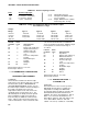
PARAM. DATA
NUMBER TYPE DESCRIPTION
01: 2 Repetitions
02: 2 Range code for V
1
(Table 9-1)
03: 2 Range code for V
2
04: 2 Differential channel
number for first
measurement
05: 2 Excitation channel
number
06: 4 Excitation voltage
(millivolts)
07: 4 Input location number
for first measurement
08: FP Multiplier
09: FP Offset
Input locations altered: 1 per measurement
*** 10 BATTERY VOLTAGE ***
FUNCTION
This instruction reads the battery voltage and
writes it to an input location. The units for
battery voltage are volts. When the batteries
are around 8 V, false battery readings of 9 to 10
V will result, and the quiescent current drain
increases from 0.7 mA to 7 mA. At 9.2 to 9.3 V,
false analog measurements are possible
(Example: 2000 mV input is measured as 2010
to 2050 mV).
PARAM. DATA
NUMBER TYPE DESCRIPTION
01: 4 Input location
Input locations altered: 1
*** 11 107 THERMISTOR PROBE ***
FUNCTION
This Instruction applies a 2 VAC excitation
voltage to Campbell Scientific's Model 107