
Measurement and Control Module Operators Manual
SECTION 8. PROCESSING AND PROGRAM CONTROL EXAMPLES
8-9
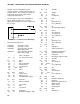
14: P95 End
15: P End Table 3
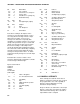
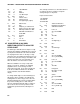
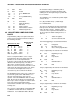
8.8 USE OF 2 FINAL STORAGE AREAS
- SAVING DATA PRIOR TO EVENT
One of the uses of 2 Final Storage Areas is to
save a fixed amount of data before and after
some event.
In this example, a load cell is measured every
second. It is assumed that at some random
interval the load will exceed 25 pounds for less
than 10 seconds. Exceeding 25 pounds is the
event to be captured. The data from the 10
seconds before the event and 10 seconds after
the event is to be saved (21 seconds including
the scan in which the load first exceeds 25
pounds).
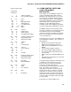
Every second the load cell is measured; hours-
minutes, seconds, and the load are output to
Final Storage Area 2 (4 values with the Array
ID). 84 locations are allocated to Final Storage
Area 2. Thus, Area 2 holds 21 seconds (4
values/second x 21 seconds = 84 locations).
When 25 pounds is exceeded, 10 is loaded into
an input location and flag 1 is set high. The
input location is used as a down counter. The
flag indicates an event has occurred and
prevents the input location from being reloaded
until 11 seconds have passed.
The down counter is decremented by 1 each
time the table is executed. When it equals 0 all
the data in Final Storage Area 2 is transferred
to Final Storage Area 1 (using Instruction 96)
and Flag 1 is set low.
The down counter is set to 10 instead of 11
because it is decremented after checking to see
if it is 0.
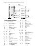
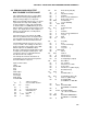
Input Location Labels:
1:FORCE LBS
2:DOWN CNT
* 1 Table 1 Programs
01: 1 Sec. Execution Interval
01: P6 Full Bridge
01: 1 Rep
02: 22 7.5 mV 60 Hz rejection Range
03: 1 IN Chan
04: 1 Excite all reps w/EXchan 1
05: 2500 mV Excitation
06: 1 Loc [:FORCE LBS]
07: 33.333 Mult
08: 0 Offset
02: P86 Do
01: 10 Set high Flag 0 (output)
03: P80 Set Active Storage Area
01: 2 Final Storage Area 2
02: 10 Array ID or location
04: P77 Real Time
01: 11 Hour-Minute,Seconds
05: P70 Sample
01: 1 Reps
02: 1 Loc FORCE LBS
06: P89 If X<=>F
01: 1 X Loc FORCE LBS
02: 3 >=
03: 25 F
04: 30 Then Do
07: P91 If Flag/Port
01: 21 Do if flag 1 is low
02: 30 Then Do
08: P86 Do
01: 11 Set high Flag 1
09: P30 Z=F
01: 10 F
02: 0 Exponent of 10
03: 2 Z Loc [:DOWN CNT ]
10: P95 End
11: P95 End
12: P89 If X<=>F
01: 2 X Loc DOWN CNT
02: 1 =
03: 0 F
04: 30 Then Do
13: P91 If Flag/Port
01: 11 Do if flag 1 is high
02: 30 Then Do
14: P96 Serial Output
01: 81 All data to other FS Area
15: P86 Do
01: 21 Set low Flag 1
16: P95 End