
Measurement and Control Module Operators Manual

SECTION 7. MEASUREMENT PROGRAMMING EXAMPLES
7-21
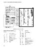
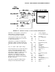
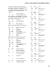
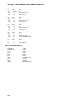
FIGURE 7.17-1. CR10/Paroscientific "T" Series Transducer Wiring Diagram
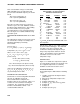
Subroutine 1, which loads the coefficients into
input locations, is called only on the first
execution following program compilation.
The temperature frequency is read on single-
ended Channel 12 and pressure is measured
on single-ended Channel 1.
Temperature, T
0
, D and C are computed in
Subroutine 2 using a generalized fourth order
polynomial equation. The form of the equation
is
F(x) = U
0
+ U(M
1
+ U(M
2
+ U(M
3
+ UM
4
))).
This form provides faster execution and greater
accuracy of the floating point math. "M
0..4
"
represents coefficients 0 through 4, and U is
defined above. With five coefficients, T
0
is the
only parameter requiring a fourth order
polynomial. To maintain the fourth order
format, zero value "dummy" coefficients are
plugged in where required for the temperature,
D, and C coefficients.
Instructions to output the readings to Final
Storage are not included in this example.
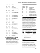
* 1 Table 1 Programs
01: 60 Sec. Execution Interval
01: P89 If X<=>F
01: 42 X Loc CMPILE CK
02: 1 =
03: 0 F
04: 1 Call Subroutine 1
02: P27 Period Average (SE)
01: 1 Rep
02: 4 Input gain=1
03: 12 IN Chan
04: 9000 No. of Cycles
05: 6 Time Out (units=.01sec)
06: 10 Loc [:UT us ]
07: 1 Mult
08: 0 Offset
03: P27 Period Average (SE)
01: 1 Rep
02: 3 Input gain=10
03: 1 IN Chan
04: 5000 No. of Cycles
05: 16 Time Out (units=.01sec)
06: 11 Loc [:TAU us ]
07: 1 Mult
08: 0 Offset