
Use and Care Manual


www.campbellhausfeld.com
Installation (Continued)
3. The line wire is the proper size
and that no other equipment is
operated from the same line. The
chart gives minimum recommended
wire sizes for compressor
installations.
Chart 2: Minimum Wire Size
Use 75°C Copper Wire
Single
Phase
Three
Phase
HP Amps 230 V
208 /
230 V
460 /
575 V
SPL
Up to 22.0
10
AWG
5.0
8
AWG
12
AWG
14
AWG
7.5
8
AWG
10
AWG
12
AWG
10.0
8
AWG
12
AWG
15.0
6
AWG
10
AWG
25.0
3
AWG
8
AWG
Recommended wire sizes may be larger
than the minimum set up by local
ordinances. If so, the larger size wire
should be used to prevent excessive
line voltage drop. The additional wire
cost is very small compared with the
cost of repairing or replacing a motor
electrically “starved” by the use of
supply wires which are too small.
GROUNDING
Improperly grounded
electrical components
are shock hazards. Make
sure all the components
are properly grounded to prevent
death or serious injury.
This product must be grounded.
Grounding reduces the risk of electrical
shock by providing an escape wire
for the electric current if short circuit
occurs. This product must be installed
and operated with a power cord or
cable that has a grounding wire.
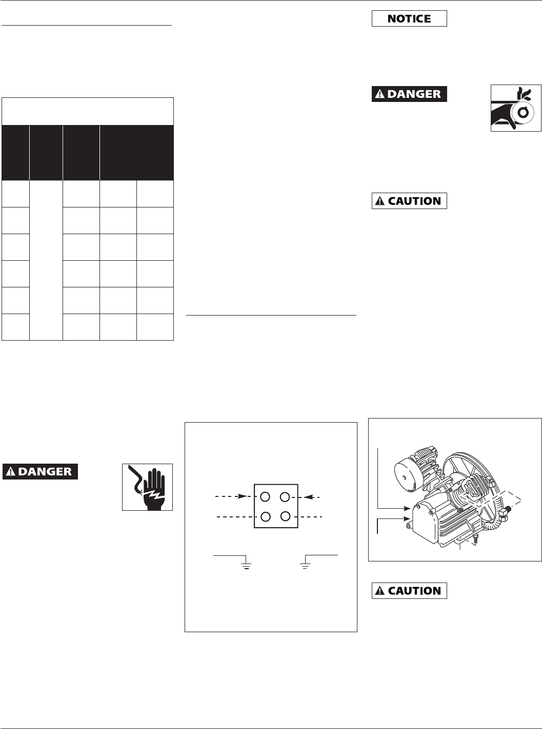
MOTOR HOOKUP
Branch circuit protection must be
provided as specified in the United
States National Electrical Code, Chapter
2, “Wiring Design and Protection.”
Article 210, using the applicable article
“For Motors and Motor Controllers,”
(Article 430, Table 430-1 52).
IMPORTANT: Overload protection
is required for all motors. Certain
motors have this protection built-in.
To determine if a motor has built-in
overload protection, refer to the frame
size on the motor nameplate.
Motors with frame size R56HZ, Y56Y
or L143T include built-in overload
protection. No additional protection is
required. Use Figure 2 wiring diagram.
DIRECTION OF ROTATION
NOTE: Improper rotation will result in
reduced unit life.
The direction of rotation must be
counterclockwise (as shown by the
arrow on the flywheel) while facing
the flywheel side of the pump. The
motor nameplate will show wiring
information for counterclockwise
rotation.
Operation
IMPORTANT: Check motor rotation
before operating the compressor.
All lubricated compressor pumps
discharge some condensed water
and oil with the compressed air.
Install appropriate water/oil removal
equipment and controls as necessary
for the intended application.
Failure to install
appropriate
water / oil removal equipment may
result in damage to machinery or
workpiece.
GUARDING
The
belt
guard provided must
be installed before
operating the unit.
All moving parts must be guarded.
All electrical covers must be installed
before turning on the power.
LUBRICATION
THIS UNIT
CONTAINS NO OIL.
Before operating compressor, fill
crankcase with compressor oil
according to the oil capacity chart.
Some residual oil may still be in the
pump leaving a thin coat on the sight
glass, however; there is not enough
oil to operate the unit. Fill pump with
single-viscosity, ISO100, non-detergent,
compressor oil.
Use part number ST126700AV,
compressor oil or Mobil 1
®
5W30 or
10W30 synthetic oil may also be used.
Add oil only through the oil fill plug.
Do NOT fill the pump through breather
cap opening as this may cause to leak
or spray out during operation.
Fill to the center of the sight gauge
(see Figure 3).
Using any other
type of oil may
shorten pump life and damage
valves.
Operating Instructions
4
L1
L2
240V
GROUND
PRESSURE
SWITCH
LINE
MOTOR
MotorMotor
Figure 2 - For Motor Frame Sizes
R56HZ, Y56Y or L143T.
Refer to Motor Nameplate
Single Phase / Three Phase
Wiring Diagram
Figure 3 - Oil Fill Diagrams
Drain on
side
Dipstick and
Oil Fill