
Operating instructions

4
Operating Instructions and Parts Manual
HVLP Paint Sprayers
(See Table 1).
www.chpower.com
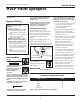
How Your HVLP
System Works
Your turbine system has three
components: the turbine unit, an air
hose and a spray gun. The turbine unit,
when connected to the correct
electrical power supply and powered
on, provides a continuous source of
clean, warm, dry, High Volume Low
Pressure air. The air hose connects the
turbine unit to the spray gun. Air flows
through the hose to the nozzle of the
specially designed spray gun.
Atomization of the coating is achieved
when the air mixes with the stream of
fluid passing through the tip/nozzle.
This low pressure atomization principle
achieves minimum misting (overspray)
to the spray environment.
The turbine blower has one air hose
outlet on the side of the unit and is
designed to run one spray gun. The
4-stage model has the capability to run
two spray guns at the same time with
an optional “Y” connector. When
using only one spray gun, always be
sure that one outlet is capped.
How Your HVLP
Spray Gun Works
Turbine Spray Guns are bleeder type
spray guns. When the turbine is turned
on, air will constantly flow through the
air cap. This helps makes the
equipment more durable. Air also
flows through the air feed tube in
order to pressurize the cup, and deliver
fluid to the tip/nozzle. When the paint
flow screw is opened and the trigger
pulled back, fluid flows through the
tip/nozzle, mixing with the air flow
delivered from the air cap. The spray
gun projects a fine atomized mist on
your work piece.
Pre-Operation
PREPARING TO USE YOUR HVLP
TURBINE SYSTEM
1. Connect the air hose to the turbine.
Pull back the spring loaded quick
disconnect coupler and insert the
male connector on the air hose into
the turbine connector. Release the
ring. Your air hose will be locked
into place. To disconnect, pull back
on the connector to release the air
hose.
If you have just
!
CAUTION
finished spraying,
the metal coupler at
the turbine end may be hot.
2. Plug the electric cord into a
correctly grounded electrical outlet.
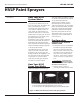
HV2100, HV2105
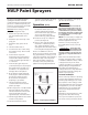
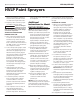
Figure 2 - Material flow knob positions and spray patterns
1. Use this position when spraying across from side to side.
2. Use this position when spraying from top to bottom.
3. Use this position for spotting small objects, corners and sharp angles.