
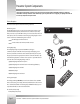
Specifications
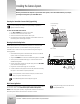

Page 6
CameraMan
®
1-CCD Presenter Camera System Installation and Operations Manual
Installing the Camera System
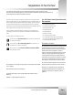
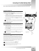
Removing the CameraMan Connector Block (Upgrade Only)
If you are performing initial installation of a system package, as opposed to an
upgrade, this will not be necessary.
To remove the CameraMan Connector Block:
1. Turn OFF the POWER switch on the back of the Camera.
2. Disconnect all cables from the back of the camera.
3. Remove the screws which hold the connector block in place.
4. Pull outward on the connector block, unplugging it from the DB-37 connector. The
Main Docking Station cable will plug into this port.
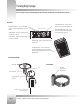
Mounting the Main Docking Station
The Main Docking Station can be mounted with any orientation, but it must be mounted
within 10' (but not closer than 1’) of the autoTRACK Camera (use only the supplied
CameraMan cable to connect the two units). Mount the Main Docking Station using the
following guidelines:
1. Mount the Main Docking Station in the desired location. Be sure to leave sufficient
space for access to the connections on the back panel.
2. Verify that the POWER switch on the front of the Main Docking Station is turned OFF.
3. Mount or place the CameraMan Power Supply in a convenient location near the
autoTRACK Docking station.
4. Plug the 5.5mm female connector from the power supply cord into the DC POWER
jack in the back of the docking station.
5. Plug the other end of the power supply into a 120 VAC outlet.
6. Connect the antennas to the appropriate connectors and position them so that they
both point in a vertical direction for optimum performance.
For best performance, locate the antennae in free space, at least 6" from the
camera, or any wires, metal surfaces, wall, etc.
See the Main Docking Station Clearance diagram on page 28.
Multi- Camera Applications
In a multi-camera application where it is desired to network multiple Cameras together, refer to
the multi-camera section of the 1-CCD General Pan/Tilt Installation and Operations
Manual. Follow the appropriate procedure, using the RS-485 connections on the back of the
Main Docking Station instead of the connections on the back of the Camera.
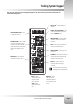
Now that you’ve identified the components of your Presenter Camera System, as well as their individual buttons, ports, and jacks,
you can begin connecting them to your CameraMan camera.
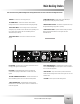
Connector Plate
DB-37 connector
Three screws through
connector plate
Back of Main Docking Station
Installing two Tracking Systems in the same area will
cause unpredictable results.