
Specifications

Page 4
CameraMan
®
1-CCD Presenter Camera System Installation and Operations Manual
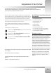
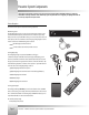
Tracking Ring Package
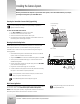
Before connecting or using your Tracking Ring package, take a moment to learn about the various buttons, switches, and jacks.
V
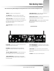
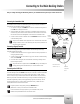
POWER INDICATOR LED – Lets you know when
power is ON (red) and when batteries are LOW
(yellow).
V
POWER SWITCH – Used to turn power pack and
Tracking Ring on and off.
V
AUDIO SWITCH – Used to turn Tracking Ring’s
microphone on and off.
V
TRACKING RING PORT – Used to connect
Tracking Ring to power pack (see page 13).
V
AUXILIARY BATTERY PACK PORT – Used to
connect the optional auxiliary battery pack
for extended use (see page 14).
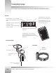
Front Sensor/Mic
Back Sensor
Clip
Tracking Ring Port
Connector
Tracking Ring Assembly
Belt Assembly
Clip power
pack pouch on
belt as shown
V
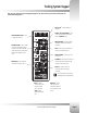
CHARGER PORT – Used to connect battery charger
to power pack.
V
RF CHANNEL SWITCH – Used to select the RF
channel the power pack will use to communicate
with the Docking Station (MUST be the same as the
Docking Station).
Power Pack
top view of power pack
Antenna