
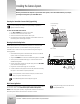
Specifications

Page 3
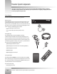
Meet Your 1-CCD Presenter Camera System
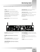
Main Docking Station
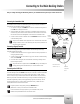
Take a look at the back of your Main Docking Station. The diagram below shows the various connections and configuration switches.
V
1
ANTENNA – RF receivers for the tracking power pack.
V
2
RF CHANNEL SELECT – Used to select which RF channel the Main
Docking Station will use to communicate with the Tracking Ring Package.
V
3
AUDIO: LEVEL SWITCH – Used to configure the level of the balanced
audio (XLR) output, available for either LINE or MIC level, depending on the
type of audio system interfacing with the CameraMan system. The
unbalanced output is LINE only.
V
4
AUDIO: LEVEL ADJUST – Used to fine tune the level of the audio
outputs..
V
5
S-VIDEO VIDEO OUT JACK – Provides direct S-Video video output
through standard mini-DIN jack (cable not provided).
SS
V
6
COMPOSITE VIDEO OUT JACK – Provides direct composite video output
through standard BNC-type jack (cable not provided).
V
7
RS-485 IN and OUT JACKS – 4-position modular handset jacks used for
RS-485 communications between the camera system and other
CameraMan devices.
V
8
PVI COM JACK – 6-conductor RJ-11 jack used for communication with the
Tracking System Keypad in hard-wired mode.
V
9
RS-232 PORT – Standard DB-9 (female) connector provides RS-232
communications capability for devices like PCs or other vendor-control
systems.
V
10
AUXILIARY COMMUNICATIONS PORT A – Provides communications to
select CameraMan peripherals. Do not use unless otherwise specified.
V
11
AUDIO: BALANCED JACK – Standard XLR-type connector provides
balanced line or mic level audio output to connect to a standard mixer or
similar audio equipment.
V
12
AUDIO: UNBALANCED JACK – Standard RCA-type connector provides
unbalanced, line level only mono audio output to connect to a standard
mixer or similar audio equipment.
V
13
BASE UNIT PORT – 37-pin D-sub connector provides communication
between the Main Docking Station and the Camera System via a 10’ multi-
conductor cable .
V
14
DC POWER – Power input for the Main Docking Station.
V
2
V
7
V
1
V
1
V
5
V
4
V
3
V
8
V
9
V
10
V
11
V
12
V
14
V
13
V
6