
Installation Guide

24
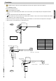
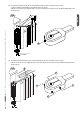
F500
F510
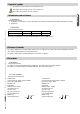
56
12
20
80
5 x ø 8,5
56
400
20
3 x M6
50
50150150
15
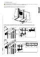
24
12
56 1212 20
80
5 x ø 8,5
56
17,5
50
80
2 x ø 6,5
Pag.
7
-
Manual code
:
119DS56EN
119DS56EN ver.
5
5 01/2015
© CAME S.p.A. -
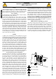
The data and information reported in this installation manual are susceptible to change at any time and without obligation on CAME S.p.A. to notify users.
ENGLISH
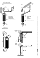
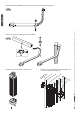
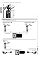
Lay the corrugated tubing needed for the connections deriving from the junction box.
N.B. the number of tubes depends on the type of system and accessories employed.
The following illustrations are only examples, given that the space available for anchoring the operator and accessories may vary
from gate to gate. It is up to the installer, thus, to choose the most suitable solution.
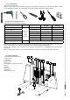
5.5 Installing the operator
Electric cable junction box
1) Trace the centre lines and external dimensions of the entire assembly in accordance with the diagrams on pages 2 and 3.
Next, mount the fl ange for the gear motor on the wall or pillar, and mount the anchor block for gear motor F500 on the gate.