
Installation Guide
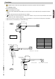

F500
F510
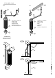
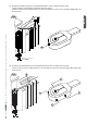
A= 100 mm max
A= 40 mm min
B= 210 mm
B= 235 mm
A
B= 350 mm
C
C min
C min= 0 mm B= 210 mm
C max= 150 mm B= 235 mm
C max
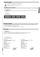
Pag.
5
-
Manual code
:
119DS56EN
119DS56EN ver.
5
5 01/2015
© CAME S.p.A. -
The data and information reported in this installation manual are susceptible to change at any time and without obligation on CAME S.p.A. to notify users.
ENGLISH
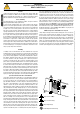
5 Installation
Before installing, do the following:
• Make sure you have suitable tubing and conduits for the electrical cables to pass through and be protected against mechanical
damage;
• Fit tubing to drain away any water leaks which may cause oxidation;
•
Make sure that any connections inside the case (that provide continuance to the protective circuit) be fitted with extra insulation
as compared to the other conductive parts inside;
• Make sure the structure of the gate is sturdy, the hinges work and that the is no friction between moving and non-moving parts;
• Make sure there is a mechanical stop for opening and closing.
Installation must be carried out by expert qualified personnel and in full compliance with current regulations.
5.1 Preliminary checks
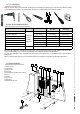
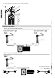
i = 230 mm max
with 90° opening angle
GATE WING WIDTH GATE WING WEIGHT
m. Kg.
0,80 150
1,20 125
1,60 100
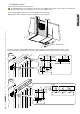
AC
40÷100 0÷150
travel=115
travel=350
Excentration minimum
Excentration maximum