1 9D S56EN AUTOMATION FOR SWING GATES INSTALLATION MANUAL F500 / F510 English EN
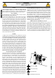
WARNING! important safety instructions for people: READ CAREFULLY! • Employ this product only for the use for which it was expressly made. Any other use is dangerous. CAME S.p.A. is not liable for any damage caused by improper, wrongful and unreasonable use • Keep these warnings together with the installation and operation manuals that come with the operator.
1 Legend of symbols This symbol tells you to read the section with particular care. This symbol tells you that the sections concern safety issues. This symbol tells you what to say to the end-users. 2.1 Intended use The ATI F500 - F510 gearmotor is specifically engineered to automate residential and condominium swing gates, even under intensive use. Pag. 3 - Manual code: 119DS56EN ver. 5 01/2015 © CAME S.p.A.
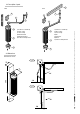
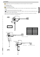
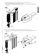
.3 Description of parts 6 F500 F510 6 5 7 5 2 1 4 1) Gearmotor central body 2) Upper casing 3) Lower casing 4) Articulated arm 5) Arm fixing bracket 6) Gearmotor fixing bracket 2 1 3 3 4.4 Dimensions Measurements in mm F500 80 85 360 90° 230 F510 90° 100 1) Gearmotor central body 2) Upper casing 3) Lower casing 4) Arm 5) Slide block 6) Runner 7) Gearmotor fixing bracket Pag. 4 - Manual code: 119DS56EN ver. 5 01/2015 © CAME S.p.A.
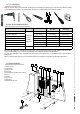
Installation Installation must be carried out by expert qualified personnel and in full compliance with current regulations. 5.1 Preliminary checks B= 350 mm A C F500 i = 230 mm max with 90° opening angle A= 40 mm min GATE WING WIDTH GATE WING WEIGHT m. Kg. 0,80 150 1,20 125 1,60 100 A C 40÷100 0÷150 B= 210 mm C min Excentration minimum C min= 0 mm B= 210 mm travel=115 B= 235 mm A= 100 mm max C max Excentration maximum travel=350 Pag. 5 - Manual code: 119DS56EN ver.
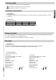
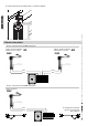
5.2 Tools and materials ENGLISH Make sure you have all the tools and materials you will need for the installation at hand to work in total safety and compliance with the current standards and regulations. The following figure illustrates the minimum equipment needed by the installer.
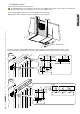
5.5 Installing the operator The following illustrations are only examples, given that the space available for anchoring the operator and accessories may vary from gate to gate. It is up to the installer, thus, to choose the most suitable solution. Electric cable junction box 1) Trace the centre lines and external dimensions of the entire assembly in accordance with the diagrams on pages 2 and 3.
2a) Use the hardware provided with the unit to join the two halves of the articulated arm together. 2b) Secure the runner to the wing and insert the straight arm. F510 3) Remove the cover at the bottom of the gear motor. 4) sing the four screws provided with the unit, install the gear motor on the flange. Fix the upper cap. ø 3,5 x 9,5 Pag. 8 - Manual code: 119DS56EN ver. 5 01/2015 © CAME S.p.A.
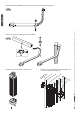
5a) - Assemble the articulated arm (A) onto the intermediate bush which is all in one with the ratiomotor shaft; - using the hardware provided with the unit, install the bracket on the gate; - make the electrical connection, supply voltage to the ratio-motor during closure and secure the arm with the M6 (B) grub screw; - fix the lower cap. F500 Pag. 9 - Manual code: 119DS56EN ver. 5 01/2015 © CAME S.p.A.
6) Complete instal-lation by mounting the upper cover with its OR gasket. 6 Electrical connections Electric connections to the ZL150N control panel 24 V D.C. gearmotor featuring delayed action on opening 24 V D.C. gearmotor featuring delayed action on closing M1 FLEX M2 FLEX Red Green Green Red - . - . % Electric connections to the ZL160N control panel 24 V D.C. gearmotor FLEX For mounting on the right side, invert the connection leads: (M-red, N-green) Red Green - . % Pag.
9.3 Maintenance Periodic maintenance ☞ Before doing any maintenance, cut off the power supply, to prevent any hazardous situations caused by accidentally activating the operator. Pag. 11 - Manual code: 119DS56EN ver. 5 01/2015 © CAME S.p.A. - The data and information reported in this installation manual are susceptible to change at any time and without obligation on CAME S.p.A. to notify users. Date Notes Signature 9.
Installer's stamp Product name Date of job Technician's signature Customer's signature 8.