
Installation Manual


Inside
Wall Switch
Outside
Wall Switch
Occupied
LED
(optional)
Panic switch
(optional)
Inside
Push to Lock
Switch
FILENAME: EMF-2 Diagram 3.vsd
DRAWING No: DRG-EMF-2_03
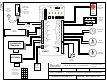
EMF-2 Diagram 3, Single Door Restroom Application (unsecured)
SCALE: NONE
DRAWN BY: DGW
REVISED: 06/08/10
DATE: 03/24/10
Camden Door Controls
5502 Timberlea Blvd
Mississauga, Ontario
L4W 2T7
12 - 24 V
AC/DC
Power
Magnetic
Contact
Switch
Fail-Safe
Electric Strike
Shown
MOV
Wire MOV
(supplied)
directly to strike
or magnet
(If Fail-Secure lock
is used, wire to
Terminals 1 & 2)
PUSH
TO
LOCK
Optional
Power
for Strike
Optional
OCCUPIED
Door
Operator
RELAY 5 CHART
To have Relay 5
shadow another
relay, set dipswitch
as shown at right
2
4
3
1
=
ON
ON ON
ON
OFF
OFF
OFF OFF
Dip
4
Dip
5
N.C.
Occupied
Signal
(LED only)
1
Timer Settings
Relay On Indicators
EMF-2
1
5
2
3
4
6
7
8
9
10
11
12
13
14
15
1
5
2
3
4
6
7
1
5
2
3
4
6
7
8
9
10
11
12
13
14
Off / On
1
2
5
7
4
6
3
8
Mode
Rel 5
Opt
2345
LED Output
12V 5V
Power
ON
NC
NC
NC
NC
NC
NO
NO
NO
NO
NO
C
C
C
C
C
Relay 1
Relay 2
Relay 3
Relay 4
Relay 5
1
2
12/24V
Power
Inputs
1
2
3
4
5
6
7
Digital I/O
terminal
strip
Assistance
Required !
!
Page 6
TO OPEN
PUSH
TO OPEN
PUSH