
Installation Manual


Turn the Key switch (or other type switch) to “Day
Mode”. If the strike is to be dogged back
mechanically, then do so. If it is to be powered all
day long, then confirm that it is powered and
released.
Now both the interior and exterior switches will open
the door when activated. The card-reader has no
effect on operation (it has been electronically de-
activated).
A new option on the EMF-2 is the provision for an
emergency “Lock Down” switch to be added. This
momentary contact switch only functions in night
mode. This test will take two persons – one to
depress the switch inside, and another person
outside to confirm the card-reader input has been
disabled. Opening the door from the inside (either
manually or automatically) will reset the system (a
N/C magnetic door contact switch is required).
Once the desired operation is achieved, proceed to
Section 4, for System Inspection Instructions.
Section 3B________________
Set-up Instructions
Unsecured Restroom (Mode 2)
This application is a shared-use single (normally
unlocked) restroom door in facilities such as nursing
homes, hospitals, shopping malls, etc. The relay
provides control of the lock, operator, and switches,
to provide the utmost in flexibility, safety for the
occupants, yet still be easy to install and program.
The door is opened automatically by pressing the
exterior wall switch. Once the door has closed,
pressing the “Push to Lock” button inside then locks
the door – the strike is energized, and the exterior
switch is removed from the circuit. To exit the
restroom, simply push the interior wall switch. The
door unlocks, opens and resets the system. Should
the door be opened manually, the magnetic contact
switch will reset the system.
Unique to the EMF-2 is the emergency input, which
allows a panic button to unlock, open the door
(optional), and send an emergency signal for
assistance. The output can be maintained or pulsed.
As an added safety feature, the EMF-2 can be set to
automatically reset (and unlock) after 15 minutes
time.
Step 1
Select
MODE 2 via the first 3 positions of the
dipswitch as shown below:
Off On
1
2
3
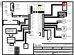
See diagram 1 for location of dipswitch, connectors,
& potentiometers.
IMPORTANT: Any changes Mode selector or
Out2
settings must be made with power off!
Step 2
Dip switch Options
Push dipswitch #6
ON when you want the panic
button to unlock the door and also open it. Leave
switch #6
OFF to enable the panic button to unlock
the door only but not open it.
Push dipswitch #7
ON, to enable the 15 minute time-
out (reset) feature. Leave in OFF position if you do
not want an automatic reset.
Use of Relay 5 is optional, and set according to
dipswitches #4 & 5. (See diagram 1 for location). A
common use in this mode would be to have Relay 5
follow the the lock relay and light an occupied sign.
By default, Relay #5 follows Relay #1.
Dipswitch # 8 is not used in this mode.
Step 3
Connections
Refer to Diagram 3 (next page) for the following
connections.
Wire all input connections to the (removable)
Input
terminal strip
(numbered 1 - 14). Firmly re-insert
connector if removed.
Next, make your connections to the
Relay Output strip
(numbered 1 – 15). (Relay 3 is not used in this
application). Re-insert connector.
The 7-pin
Digital I/O strip provides either 12V DC or
5V DC on Terminals 6 & 7 for lighting an “Occupied”
LED. This output is present whenever the door is
locked. Select output voltage using jumper as shown
below:
LED Output
12V 5V
Finally, connect 12 or 24 Volt AC or DC supply to
terminals 1 & 2 of the 2-pin Power Connector.
(The terminals are not polarity sensitive).
Pa
g
e 5 of 19