
Installation Manual


FILENAME: EMF-2 Diagram 1.vsd
DRAWING No: DRG-EMF-2_01
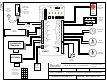
EMF-2 Diagram 1, Electrical and Mechanical
SCALE: NONE
DRAWN BY: DGW
REVISED:
DATE: 03/24/10
Camden Door Controls
5502 Timberlea Blvd
Mississauga, Ontario
L4W 2T7
RELAY 5 CHART
To have Relay 5
shadow another
relay, set dipswitch
as shown at right
2
4
3
1
=
ON
ON ON
ON
OFF
OFF
OFF OFF
Dip
4
Dip
5
Page 2
1" (25 mm)
6 7/8" (173 mm)
2 7/8" (72 mm)
6 13/16" (160 mm)
Trouble
Output
1
Timer Settings
Relay On Indicators
1
5
2
3
4
6
7
8
9
10
11
12
13
14
15
1
5
2
3
4
6
7
1
5
2
3
4
6
7
8
9
10
11
12
13
14
Off / On
1
2
5
7
4
6
3
8
Mode
Rel 5
Opt
2345
LED Output
12V 5V
Power
ON
NC
NC
NC
NC
NC
NO
NO
NO
NO
NO
C
C
C
C
C
Relay 1
Relay 2
Relay 3
Relay 4
Relay 5
1
2
12/24V
Power
Inputs
1
2
3
4
5
6
7
Digital
In/Out
terminal
strip
Input
disables
Door #2
EMF-2
P1
P4
P2
P3
Side View
Top View
Connector Terminal Label Function
1 Power Input
P1
2 Power Input
12/24 Volts AC/DC
Non-polarized
1 Ground
2 Blue (or Brown)
3 N/C (or Yellow)
4 CR Power +5V
5 Orange (output 1)
6 Output 2
P2
7 Ground 2
Card-Reader
Input
(aka - Digital
Connector)
1 Dry 1 Input
2 Dry 1 Input
Non-powered Input 1
3 Dry 2 Input
4 Dry 2 Input
Non-powered Input 2
5 Dry 3 Input
6 Dry 3 Input
Non-powered Input 3
7 Dry 4 Input
8 Dry 4 Input
Non-powered Input 4
9 Dry 5 Input
10 Dry 5 Input
Non-powered Input 5
11 Dry 6 Input
12 Dry 6 Input
Non-powered Input 6
13 Dry 7 Input
P3
14 Dry 7 Input
Non-powered Input 7
1 Relay 1 – NC
2 Relay 1 – COM
3 Relay 1 – NO
Form C
4 Relay 2 – NC
5 Relay 2 – COM
6 Relay 2 – NO
Form C
7 Relay 3 – NC
8 Relay 3 – COM
9 Relay 3 – NO
Form C
10 Relay 4 – NC
11 Relay 4 – COM
12 Relay 4 – NO
Form C
13 Relay 5 – NC
14 Relay 5 – COM
P4
15 Relay 5 – NO
Form C
NOTE: Pin 2 Connector. When connecting to Camden Card Reader in ABM Mode it is
possible to read all cards by wiring the Blue wire to Pin 2, or only Cards beginning with a
4, 5, & 6 by wiring the Brown wire (Data) to Pin 2, and the yellow wire (Clock) to pin 3.
06/08/10