
Installation Manual


Inside
Wall Switch
Door #1
Card Reader
Door #1
Lock Down
switch
disables
both
door
Inputs
FILENAME: EMF-2 Diagram 8.vsd
DRAWING No: DRG-EMF-2_08
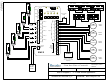
EMF-2 Diagram 8, 2 Door Mantrap Application
SCALE: NONE
DRAWN BY: DGW
REVISED: 05/04/11
DATE: 03/24/10
Camden Door Controls
5502 Timberlea Blvd
Mississauga, Ontario
L4W 2T7
12 - 24 V
AC/DC
Power
Magnetic Contact Switch
Door #2
Fail-Secure
Electric Strikes
Shown
(If Fail-Safe locks are used,
wire to Terminals 1 & 2, and 7 & 8)
Door #1 Lock
RELAY 5 CHART
To have Relay 5
shadow another
relay, set dipswitch
as shown at right
2
4
3
1
=
ON
ON ON
ON
OFF
OFF
OFF OFF
Dip
4
Dip
5
Page 16
TO OPEN
PUSH
Door #2
Operator
Door #1
Operator
Door #2 Lock
TO OPEN
PUSH
Inside
Wall Switch
Door #2
Card Reader
Door #2
Power for Lock
Power for Lock
LOCK
DOWN
N.C.
N.C.
Magnetic
Contact
Switch
Door #1
Trouble
Trouble output after 5
minutes of door ajar.
Select 5V or 12V
output with jumper
STEP
HERE
ONLY
Trouble
Output
1
Timer Settings
Relay On Indicators
EMF-2
1
5
2
3
4
6
7
8
9
10
11
12
13
14
15
1
5
2
3
4
6
7
1
5
2
3
4
6
7
8
9
10
11
12
13
14
Off / On
1
2
5
7
4
6
3
8
Mode
Rel 5
Opt
2345
LED Output
12V 5V
Power
ON
NC
NC
NC
NC
NC
NO
NO
NO
NO
NO
C
C
C
C
C
Relay 1
Relay 2
Relay 3
Relay 4
Relay 5
1
2
12/24V
Power
Inputs
1
2
3
4
5
6
7
Digital
In/Out
terminal
strip
Input
disables
Door #2
Normally Open input
will disable Door #2
Common device is a
specially constructed
electric switch mat.