
Installation Manual


Door 2
Switch
Door 1
Switch
Door 3
Switch
FILENAME: EMF-2 Diagram 7.vsd
DRAWING No: DRG-EMF-2_07
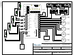
EMF-2 Diagram 7, 2 - 5 Door Airlock Application
SCALE: NONE
DRAWN BY: DGW
REVISED:
DATE: 03/24/10
Camden Door Controls
5502 Timberlea Blvd
Mississauga, Ontario
L4W 2T7
12 - 24 V
AC/DC
Power
Page 14
Door 1 Contact
Trouble
Trouble output after 5
minutes of door ajar.
Select 5V or 12V output
with jumper
1
Timer Settings
Relay On Indicators
EMF-2
1
5
2
3
4
6
7
8
9
10
11
12
13
14
15
1
5
2
3
4
6
7
1
5
2
3
4
6
7
8
9
10
11
12
13
14
Off / On
1
2
5
7
4
6
3
8
Mode
Rel 5
Opt
2345
LED Output
12V 5V
Power
ON
NC
NC
NC
NC
NC
NO
NO
NO
NO
NO
C
C
C
C
C
Relay 1
Relay 2
Relay 3
Relay 4
Relay 5
1
2
12/24V
Power
Inputs
1
2
3
4
5
6
7
Digital
In/Out
terminal
strip
TO UNLOCK
PUSH
TO UNLOCK
PUSH
TO UNLOCK
PUSH
TO UNLOCK
PUSH
TO UNLOCK
PUSH
N.C.
N.C.
N.C.
N.C.
N.C.
Power
for Strike
Power
for Strike
Power
for Strike
Power
for Strike
Power
for Strike
Door 4
Switch
Door 5
Switch
Door 4 Contact Door 5 Contact
Door 2 Contact Door 3 Contact
Clear Trouble
Switch