
Installation Manual


Section 3D________________
Set-up Instructions
2-Door Restroom (Mode 4)
This application is a shared-use (normally unlocked)
restroom between two suites (and therefore utilizing
two doors), in facilities such as nursing homes &
hospitals, etc. The relay provides control of both
locks, operators, and all switches, to provide the
utmost in flexibility, safety for the occupants, yet still
be easy to install and program.
Either door is opened automatically by pressing the
respective exterior wall switch. Once the door has
closed, pressing either “Push to Lock” button inside
then locks both doors – the strike is energized, and
exterior switches are removed from the circuit. To
exit the restroom, simply push either interior wall
switch. The respective door unlocks, opens and
resets the system. Should either door be opened
manually, the magnetic contact switch will reset the
system.
Unique to the EMF-2 is the emergency input, which
allows a panic button to unlock, open (one or both)
door(s), (optional), and send an emergency signal for
assistance. The output can be maintained or pulsed.
As an added safety feature, the EMF-2 can be set to
automatically reset (and unlock) after 15 minutes
time.
It is strongly encouraged to utilize the dry contact
output (Relay #5) or the LED output to indicate
“Occupied” on the exterior of both doors to let others
know the restroom is in use.
Step 1
Select
MODE 4 via the first 3 positions of the
dipswitch as shown below:
Off On
1
2
3
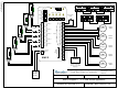
See diagram 1 for location of dipswitch, connectors,
& potentiometers.
IMPORTANT: Any changes Mode selector or
Out2
settings must be made with power off!
Step 2
Dip switch Options
Leave switch #6
OFF to enable the panic button to
unlock the door only, but not open it. Put dipswitch
#6
ON when you want the panic button to unlock the
door and also open it. Furthermore, if dipswitch #6 is
set to
ON, and dipswitch # 8 is set to OFF, then only
the last door used will open. Setting dipswitch #8 ON,
will open both doors simultaneously.
Push dipswitch #7
ON, to enable the 15 minute Time-
out (reset) feature. Leave in
OFF position if you do
not want an automatic reset.
Use of Relay 5 is optional, and set according to
dipswitches #4 & 5. (See diagram 1 for location). A
common use in this mode would be to have Relay 5
follow the lock relay and light an occupied sign. It
could also be utilized for the second door lock, rather
than connecting both door locks to Relay #1 output.
By default, Relay #5 follows Relay #1.
Step 3
Connections
Refer to Diagram 5 (page 10) for the following
connections.
Wire all input connections to the (removable)
Input
terminal strip (numbered 1 - 14). Firmly re-insert
connector if removed.
Next, make your connections to the
relay output strip
(numbered 1 – 15). Both door locks may be
connected to relay #1 or, wire one lock to Relay #1
and the other to Relay #5. Re-insert connector.
The 7-pin
Digital I/O strip provides either 12V DC or
5V DC on Terminals 6 & 7 for lighting “Occupied”
LED’s. This output is present whenever the door is
locked. Select output voltage using jumper as shown
below:
LED Output
12V 5V
Finally, connect 12 or 24 Volt AC or DC supply to
terminals 1 & 2 of the 2-pin Power Connector.
(The terminals are not polarity sensitive).
Step 4 Adjustments
In this application, you will use pots 2 – 5. Pot #1 has
no effect.
Timer 2 Operator Delay-on-activate
Timer 3 Operator Delay-on-release
Timer 4 Panic Relay (#4) ON time
Timer 5 Panic Relay (#4) OFF time
Note: If pot 5 is turned to zero,
relay will be on steady
Apply power to door operators, EMF-2, and all
connected equipment (ie – strikes, lights, etc).
Observe the red Power LED on the unit, which
should light. If not, re-confirm proper voltage and/or
terminal strip connection.
Pa
g
e 11 of 19