MODEL HVP (HIGH VOLUME PULSE) DUST COLLECTOR BAGHOUSE INSTRUCTION, OPERATIONS & MAINTENANCE MANUAL CAMCORP, INC.
TABLE OF CONTENTS RECEIVING & INSPECTION OF UNIT ....................................................................... 1-1 SAFETY INFORMATION ............................................................................................. 2-1 OPERATING PRINCIPLE & SECTION/PARTS DETAIL........................................... 3-1 ON SITE STORAGE RECOMMENDATIONS ............................................................. 4-1 SETTING UP YOUR UNIT.............................................................
RECEIVING YOUR UNIT Prior to accepting shipment, care must be taken to inspect all equipment received both for proper count and for damage. Any and all irregularities must be noted on the carriers’ copy of the shipping receipt to assist in settling any claims for damage or shortages. All equipment is shipped FOB point of origin whether on a prepaid or collect freight basis. ANY CLAIM FOR DAMAGE IN TRANSIT OR SHORTAGES MUST BE BROUGHT AGAINST THE CARRIER BY THE PURCHASER.
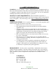
*** SAFETY INFORMATION *** WARNING!!! - Do not attempt to operate or maintain this piece of equipment until you have read and understand all of the safety information included in the manual. This piece of equipment contains moving which can cause serious injury. If you do not understand anything in this manual seek assistance prior to operations.
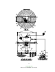
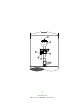
OPERATION PRINCIPLE A. Solids laden air or gases enter the unit at the hopper or housing inlet. B. Air passes through the filter media. C. Solids are retained on the filter media surface. D. Cleaning consists of a rotating pulse arm with nozzles positioned over the bags that randomly pulses 7-8” PSI air into the bags that reverses the airflow. 1. This momentarily takes a row of bags off stream through pressure reversal. 2. Flexing filter bags. 3.
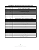
CAMCORP HVP (High Volume Pulse) Cleaning Mechanism Components Item Quantity Description 1A 1B 2 3 4 5 6 7 8 9 10 11 12 13 14 15 16 17 18 19 20 21 22 23 24 25 1 1 1 1 1 1 1 1 1 1 1 1 1 1 2 1 1 1 1 1 1 1 1 1 1 1 Pulse Arm (Size Determined by Model) Pulse Arm (Size Determined by Model) 8” OD Rotary Spool Section 8” OD Arm Rotation Support 8” Diaphragm Valve Solenoid Valve – NEMA 4 or NEMA 9 Tank Assembly (Size Determined by Model) 2” Weighted Relief Valve Solid State Timer PD Pump Discharge Silencer (Size
3-3 CAMCORP, INC.
3-4 CAMCORP, INC.
ON SITE STORAGE RECOMMENDATIONS I. Baghouse and Housing 1. Housing can be stored outside. 2. Equipment must be blocked up to keep the flanges out of the dirt. 3. Many units are supplied with a plain finish bare steel interior. If storage of more than two week is anticipated, the interior should be prime coated before storage. 4. Covering the unit with a tarp is recommended to keep the interior from rusting or corroding as well as keeping the finish in new condition.
ON SITE STORAGE RECOMMENDATIONS (continued) IV. Fan and Fan Accessories 1. Fans can be stored outside on a pallet or skid to keep out of water and dirt. 2. Equipment should be covered with a tarp to protect from the bags. 3. Fan silencers, outlet dampers, and inlet boxes should also be tarped and stored on a pallet or skid. V. Ducting 1. Ducting can be stored outside on a pallet or skid to keep it off the ground. It should be positioned so that water does not sit in the equipment. 2.
ON SITE STORAGE RECOMMENDATIONS (continued) IX. Butterfly (Wafer Valve) 1. All limit switches, solenoids, and air cylinder ports must be capped and taped to prevent any moisture or dirt from entering. 2. Unit can be stored outside provided it is covered with a tarp and is on a pallet or skid to keep it out of the water and dirt and sunlight. X. Level Indicators Store these items inside a cool dry area protected from rodents XI.
SETTING UP YOUR UNIT CAMCORP dust collectors are shipped in various states of assembly depending on the size and configuration of the unit. Before attempting to move the dust collector or any of its sections, review both the certified general assembly drawing supplied with your unit and the rigging and lifting guidelines included in this manual.
Platform Installation: The platform, ladder, handrail, and bracing are to be installed as shown on the special platform detail provided. Use the part ID’s to locate the parts in the proper location. Explosion Vents (where applicable): 1. Figure 6 – The explosion vents are attached with a minimum of standard steel fasteners for shipment. THESE MUST BE REMOVED and the PVC Bolts installed that are included in the shipment. Extreme care should be exercised when installing the PVC Bolts as they are very fragile.
Electrical: A 120-volt, 60-Hertz, 1-Amp circuit is required to operate the dust collector’s Solid State Timer. A 230/460V 3-phase circuit is required to run the Pulse Arm drive motor and the Cleaning Air PD (Positive Displacement) pump motor. Note: The Adjustable Timer needs to be mounting were the Pressure Gauge on the PD Pump is visible. 5-3 CAMCORP, INC.
Gauges: Check the pressure differential gauge to make sure that the high-pressure tap is connected below the tube sheet and the low-pressure tap is connected above the tube sheet. Verify that the gauge have been zeroed prior to connection when it is in its permanent mounting position. Cleaning Air PD Pump: The PD Pump must be install at the base of the filter to accommodate installation of the Air Supply line. Securely anchor in permanent location.
TOP LOAD BAG AND CAGE INSTALLATION 1. Inspect the cage for any signs of damage, warping, bent wires, or missing welds. 2. Inspect the filter bag for any signs of mold, mildew, ripped seams, or holes. 3. Lower the closed end of the bag through the hole in the tube sheet. 4. With your hands, “kidney shape” the snap band bag top in order to fit and align it within the tube sheet hole. 5. Fit the groove of the snap band to the I.D. of the tube sheet hole and allow it to expand and audibly snap into place.
START-UP CHECKLIST 1. Installation Make sure the unit is secured to grade. The ladder(s) and platform(s) must be tightened and set up according to OSHA requirements. Ducting and piping must be secured and routed out of the way of traffic whenever possible to avoid injury. Ducting must also be free of all debris including moisture. 2. Interior of the dirty air plenum A. Make sure that the filter bag assemblies hang straight and the bottoms do not touch each other or any part of the collector interior.
5. Exterior of dust collector A. Access doors, inspection ports, and relief vents should seat effectively to prevent leakage. B. All bolts must be properly tightened. C. Operate any equipment connected to the dust discharge of the dust collector. Check the rotation of any motor driven equipment such as rotary airlocks, horizontal unloading valves, live bottom bin activators, and screw conveyors. Check slide gates and butterfly valves for binding. 6.
START-UP DUST CONTROL SYSTEMS 1. Fan or blower system A. Start the fan or blower and check rotation. B. Check dust pickup points for proper suction; balance airflow in individual ducts. C. Check for air leakage at all flanged connections. 2. Equipment start-up sequence A. Start the pulse arm drive motor (direction of rotation is not critical). B. Start the PD pump motor and check rotation. C. Adjust timer Off-time by watching pressure gauge on PD pump. The pressure in the tank should peak between 7-8 PSI.
H. Observe the manometer or magnahelic differential pressure gauge reading. As the new filter bags become coated with dust, the efficiency of the filtering action increases, and the differential pressure across the filter bags will also increase. Slowly bring the collector to full load and note the final pressure drop across the filter bags. Never allow the pressure drop across the filter bags to exceed 17” w.g. maximum or filter bags may collapse. I.
SHUT-DOWN PROCEDURES 1. Dust control systems Reverse start-up procedure, shut down fan, then after 5 or 10 minute delay, shut down the PD pump and pulse arm drive motor. 2. Pneumatic systems Reverse start-up procedure, shut down fan, then after 5 or 10 minute delay, shut down the reverse air fan and sweep arm drive motor. 9-1 CAMCORP, INC.
TROUBLESHOOTING THE DUST COLLECTOR I. Excessive pressure drop across filter bags The differential pressure gauge or manometer on your dust collector should read 6” w.g. or less. Higher readings and/or steadily increasing readings are an indication that the main airflow through the dust collector may be restricted, and a potential process problem such as poor suction at duct pickup points may exist. In extreme cases (over 17” w.g.) filter bags will be damaged. Check the following: A.
TROUBLESHOOTING THE DUST COLLECTOR (continued) Visually inspect the bags for heavy caking; if caking is evident, see the note below and take the necessary action to clean the bags. Next, measure the main airflow with a pitot tube or equivalent devise and compare with the original volume for which the unit was designed. If the flow is too high, cut back the main fan to prevent a recurrence of the problem. 3.
TROUBLESHOOTING THE DUST COLLECTOR (continued) II. Extremely Low Pressure Drop A. Pressure Gauge Check the differential pressure gauge or manometer and the tubing leading to the dust collector as in I-A of this section. B. Holes in Filter Bags or Bags Incorrectly Installed. Inspect the filter bags for holes, rips, tears, or excessive wear. Make sure that the filter bags were installed correctly according to the “Bag & Cage Installation” section. C.
TROUBLESHOOTING THE DUST COLLECTOR (continued) B. Residual Dust If dust has gotten into the clean air plenum because of a dropped or torn bag, hole in tube sheet, etc., the pulse air may stir up the dust and allow it to escape into the clean air exhaust. Residual dust may also be driven down inside the filter bags by the pulse air; if the filter bags are filled with several inches of dust, clean both the clean air plenum and the filter bags to avoid further problems. V.
TROUBLESHOOTING THE CLEANING MECHANISM 1. Diaphragm Valve – Pulsing Failure. The Diaphragm assembly consists of (3) components. The main diaphragm valve, the secondary diaphragm valve, and the solenoid valve. Troubleshooting recommendations as follows: A. Main Diaphragm and Secondary Diaphragm: 1. Diaphragm Valve Bleeding Air – Disassemble and inspect both diaphragms for ruptured valves or air bleed holes are restricted. (Reference attached manual) Replace with a repair kit if necessary. 2.
3. Positive Displacement (PD) Pump - Following is a list of possible Symptoms and Troubleshooting Solutions.
Symptom Poor Performance Leaking Oil Possible Causes Restricted Inlet Possible Sources Clogged Filter Element Collapsed Inlet Hose Erroneous Pressure Loose Gauge Connection Gauge Movement Damaged Gauge Inaccurately Calibrated Air Leakage Improper Relief Valve Setting Blown Gaskets Loose Piping Joints Insufficient Rotor Speed Wrong Sheave Set Wrong Motor Speed Slipping Belts Excessive Rotor Clearances Abrasive Wear of Rotor Surfaces Rotor “Lag” Timed Failed Oil Seals Foreign Material in Seal Bor
Symptom Overheating Possible Causes Excessive Pressure Ratio Possible Sources Clogged Filter Element Collapsed Inlet Hose Clogged Dust Vent Filter Undersized Dust Vent Filter Clogged Diffusion Pads Wrong Sheave Set Wrong Motor Speed Slipping Belts Insufficient Rotor Speed 4. Pulse Arm Drive – Motor not rotating. A. Remove the motor from the gear drive and check for proper operation. If the motor does not rotate, repair or replace. B.
SAFETY RECOMMENDATIONS Because this unit may be under pressure, do not attempt to open any device doors or panels while fans or blowers are running. If your unit is equipped with a discharge auger or an airlock, be sure chain guards are installed before start-up and servicing is attempted only after electrical power is locked out. While servicing the filter, it is very important that there are no open flames, welding or grinding sparks.
ROUTINE MAINTENANCE A. Inspection Frequency will vary as widely as there are operating conditions. In general proceed as follows: 1. Daily – Check unit differential pressure. 2. Weekly – Verify that the pulse arm drive and PD Pump are operating properly. 3. Monthly – Lubricate fan, rotary valve and screw conveyor. Check seals on latter two for dust loss. 4. Quarterly – On Top Access Units, check for dust accumulation in clean air plenum. B. Repairs 1.
COMPONENT IOM MANUALS MORSE RAIDER WORM GEAR SPEED REDUCER (Maintenance)......................... 1-8 MARTIN TORQUE LIMITER CLUTCH ................................................................... 7-10 AMERICAN CONTROL PRODUCTS TIMER ........................................................ 11-12 ROOTS POSITIVE DISPLACEMENT BLOWER (IOM)......................................... 13-40 14-1 CAMCORP, INC.
Emerson Power Transmission FORM P O Box 687 MAYSVILLE, KY 41056 Phone: 800-626-2093 www.emerson-ept.com 8721 March 2003 ® MAINTENANCE INSTRUCTIONS FOR WORM GEAR SPEED REDUCERS Center Distances 1.33, 1.54, 1.75, 2.06, 2.37, 2.62, 3.00, 3.25 3.75, 4.50, 5.16 and 6.
INTRODUCTION The following instructions apply to RAIDER® Worm Gear Speed Reducers. When ordering parts or requesting information be sure to provide all the data stamped on the reducer nameplate. EQUIPMENT REQUIRED In addition to standard Mechanic's tools, the following equipment is required: arbor press, wheel puller, torque wrench, dial indicator, seal driver, bluing, adhesive sealant, snap ring pliers for internal and external rings.
3. High speed shaft (worm shaft) removal: 1.33 C.D. through 3.25 C.D.: C-Flange units Use a small chisel to make a groove in the stamped steel cover opposite the motor flange. Pry off the cover. Remove internal snap ring from housing bore. Remove motor flange. Using a plastic hammer, gently tap on the motor end of the shaft to feed worm shaft assembly through housing and out. 3.75 C.D. through 6.00 C.D.: Remove motor flange. Remove seal cage opposite motor face. Keep shims with seal cage for reassembly.
D. Work seal loose. Be careful to keep all metal or dirt particles from entering unit. Remove old sealing compound from seal seat if it is present. Also remove burrs and sharp edges from shaft. Clean with rag moistened with solvent. Do not use abrasive material on shaft seal contacting surface. E. Protect seal lips when handling; seal leakage will result if these are damaged. If a seal with rubber coating on the outside diameter (O.D.) is used, no sealant is necessary. If no rubber coating is on seal O.D.
Lubricate Bearing Bores of Housing. Sub-assemble the rear bearing onto worm shaft. Lock rear bearing onto shaft with external snap ring. Insert shaft assembly from opposite extension end into housing until bearing is seated against shoulder in bore. Lock shaft assembly in housing bore with internal snap ring. Coat outside diameter of stamped steel endcover with adhesive sealant (except, if end cover is rubber coated DO NOT use sealant) and press into input bore opposite extension, until flush with housing.
4. Seals - To reassemble seals to unit, see Parts Service Steps on Page 3. 5. Motorized Coupling Adapter Reassemble using the original dimensions determined under "General Instructions" on Page 2. 6. Final Inspection A. Turn the gear train by hand as a final check. B. Re-install reducer and accessories. C. Fill reducer with the recommended oil to the appropriate level. See the installation instructions supplied with the reducer. D.
Martin BULLETIN TL-1 SPROCKET & GEAR, INC.
Torque-Limiter Clutches Martin TORQUE-LIMITER Torque-Limiter clutches may be used with a sprocket, gear, sheave, flange or other driven member. It is recommended that the rubbing sides of the driven member be ground to provide a smooth rubbing surface of 65 to 125 micro-inches. See torque rating table on following page. clutch offers thrifty overload protection that’s easy to adjust.
Torque-Limiter Clutches TORQUE-LIMITER CLUTCHES Stock Plate Sprockets with Ground Each assembled unit contains one spring. Higher ratings can be obtained by ordering a second spring to nest in the original one. Bushings need to be ordered separately if required. G E Face and Bored to Fit the B E D C Torque Limiter J L K UNIT TT25 A The rubbing sides of the center member should be ground parallel — 65 to 125 micro-inches.
Coupling Safety WARNING & SAFETY REMINDER Safety must be considered a basic factor in machinery operation at all times. Most accidents are the result of carelessness or negligence. All rotating power transmission products are potentially dangerous and must be guarded by the contractor, installer, purchaser, owner, and user as required by applicable laws, regulations, standards, and good safety practice.
Made-to-Order and Stock Products Screw Conveyor Components and Accessories SCREWS HOT DIPPED GALVANIZED ANGLE FLANGED “U” TROUGH MILD STEEL AND GALVANIZED FORM FLANGED “U” TROUGH MILD STEEL AND GALVANIZED SECTIONAL FLIGHTS MILD STEEL TUBULAR HOUSING MILD STEEL AND GALVANIZED TROUGH ENDS DISCHARGE GATE FLAT RACK AND PINION INLETS AND DISCHARGE SPOUTS MILD STEEL AND GALVANIZED SHAFT SEAL WASTE PACK HELICOID SCREWS RIGHT HAND AND LEFT HAND MILD STEEL AND GALVANIZED ELEVATOR BUCKETS SHAFT SEAL PLATE
Made-to-Order and Stock Products Stock QD V-Belt Sheaves All Steel Stock Sprockets BORED TO SIZE HARDENED TEETH DOUBLE SINGLE HARDEND TEETH SABER TOOTH® HARDENED TEETH QD TRIPLE Stock Bushings/Hubs BUSHINGS TYPE QD STEEL WITH KEYSEAT SIZE SF-N “3V” HI-CAP® “5V” HI-CAP® “8V” HI-CAP Stock Tapered Bushed V-Belt Sheaves TAPERED BUSHING QD IDLER BUDSHING Stock Gears/Steel and Cast CONVENTIONAL C SECTION TAPER BUSHED “3V” HI-CAP® TAPER BUSHED CONVENTIONAL B SECTION TAPER BUSHED Stock Couplings/C
Extensive stockyards of screws are available for quick shipment. A broad inventory of equipment ensures prompt worldwide delivery. Quality material and an experienced staff means a rapid turnaround for you, our customer. SERVICE CENTERS WORLDWIDE USA Mini Manufacturing Centers General Offices Sales and Manufacturing Boston, MA Arlington, TX 3100 Sprocket Drive 76015-2898 P.O.
TIMING MODULE FULLY SOLID STATE ENCAPSULATED ONE AMPERE LOAD RATING E75633 LR46938 Series 606 - PROGRAMMABLE RECYCLE CMOS DIGITAL CIRCUITRY • • • • Life Expectancy –unlimited Environment Protected Tamper Proof No False Operate • • • Small Size – 2"x 2" x 53/64" Lightweight – approximately 2.5 oz. Rugged Application of power simultaneously initiates timing and turns the load ON. The load remains ON for the preset ON time period after which it turns OFF for the preset OFF time period.
CALIBRATION RESISTANCE VS TIME ACCESSORIES – AVAILABLE FROM STOCK ORDER P/N: PM – 1M 1 MEGOHM ± 20% PM – 100K 100 KOHM ± 20% TYPICAL WIRING OUTLINE DRAWING Order bracket mount model as: 606BM – (T1) (T2) (V) (P1) (P2) 606RBM (T1) (T2) (V) (P1) (P2) MADE IN USA AMERICAN CONTROL PRODUCTS A DIV. OF PRECISION TIMER CO., INC. 47 WESTBROOK INDUSTRIAL PARK ROAD WESTBROOK, CT. 06498 PHONE: (860)399-6253 FAX:(860)399-5619 EMAIL:info@precisiontimer.com Web Site: precisiontimer.
INSTALLATION OPERATION MAINTENANCE BLOWERS EXHAUSTERS COMPRESSORS ROOTS ™ US $3.00, Canada $4.50 Universal RAI®, URAI-DSL, URAI-G and Metric Series Contents Information Summary . . . . . . . . . . . . . . . . . . . . . . . . . . . . 1 Inspection & Maintenance. . . . . . . . . . . . . . . . . . . . . . . . 11 Safety Precautions. . . . . . . . . . . . . . . . . . . . . . . . . . . . . . . 3 Figures. . . . . . . . . . . . . . . . . . . . . . . . . . . . . . . . . . . 12-15 Operating Limitations. . . .
ROOTS® products are sold subject to the current General Terms of Sale, GTS-5001 and Warranty Policy WP-5020. Copies are available upon request. Contact your local ROOTS Office or ROOTS Customer Service Hot Line 1-877-363-ROOT(S) (7668) or direct 281-966-4700.
Safety Precautions It is important that all personnel observe safety precautions to minimize the chances of injury. Among many considerations, the following should be particularly noted: • • Blower casing and associated piping or accessories may become hot enough to cause major skin burns on contact. Internal and external rotating parts of the blower and driving equipment can produce serious physical injuries.
Installation ROOTS blowers & exhausters are treated after factory assembly to protect against normal atmospheric corrosion. The maximum period of internal protection is considered to be one year under average conditions, if shipping plugs & seals are not removed. Protection against chemical or salt water atmosphere is not provided. Avoid opening the unit until ready to start installation, as corrosion protection will be quickly lost due to evaporation.
installation can be obtained by setting the baseplate on a concrete slab that is rigid and free of vibration, and leveling the top of the base carefully in two directions so that it is free of twist. The slab must be provided with suitable anchor bolts. The use of grouting under and partly inside the leveled and shimmed base is recommended. It is possible for a base-mounted assembly to become twisted during shipment, thus disturbing the original alignment.
Acceptable Blower Drive Arrangement Options ACCEPTABLE UNACCEPTABLE Top Shaft DISCHARGE Top Shaft INLET DISCHARGE Motor On Inlet Side of Blower (Top Shaft) DISCHARGE Motor On Discharge Side of Blower (Top Shaft) INLET DISCHARGE Bottom Shaft INLET Bottom Shaft smaller than unit connections. In addition, make sure it is free of scale, cuttings, weld beads, or foreign material of any kind.
Technical Supplement for URAI® Gas Blowers Technical Supplement for 32, 33, 36, 42, 45, 47, 53, 56, 59, 65, 68, 615 Universal RAI-G blowers ROOTS Universal RAI-G rotary positive gas blowers are a design extension of the basic Universal RAI blower model. URAI-G blower uses (4) mechanical seals in place of the standard inboard lip seals to minimize gas leakage into the atmosphere. The seal vent chambers are plugged.
Lubrication For Units with a Grease Lubricated Drive End and is drained downward. A simple but very effective lubrication system is employed on the drive shaft end bearings. Hydraulic pressure relief fittings are provided to vent any excess grease, preventing pressure build-up on the seals. A restriction plug and metering orifice prevent loss of lubricant from initial surges in lubricant pressure but permit venting excess lubricant under steadily rising pressures.
Operation Before operating a blower under power for the first time, recheck the unit and the installation thoroughly to reduce the likelihood of avoidable troubles. Use the following procedure check list as a guide, but consider any other special conditions in the installation. J J J J J J J J Be certain that no bolts, tools, rags, or debris have been left in the blower air chamber or piping.
Troubleshooting Checklist Trouble Item Possible Cause No flow 1 Speed too low 2 Wrong rotation 3 4 Obstruction in piping Speed too low 5 Excessive pressure rise 6 7 Obstruction in piping Excessive slip Low capacity Excessive power Damage to bearings or gears Vibration Driver stops, or will not start Excessive breather Blow-by or excessive oil leakage to vent area Excessive oil leakage in vent area 8 9 10 Speed too high Excessive pressure rise Impeller rubbing 11 12 13 Scale, sludge, r
Inspection & Maintenance: Universal RAI® series blowers A good program of consistent inspection and maintenance is the most reliable method of minimizing repairs to a blower. A simple record of services and dates will help keep this work on a regular schedule. Basic service needs are: any reason. Some oil seal leakage may occur since an oil film under the lip is required for proper operation. Periodically leaked oil should be wiped off from surfaces.
Figure 2 - Allowable Overhung Loads for V-Belt Drives Universal RAI®/URAI®-J Units Belt Pull lbs = 252100 • Motor HP Blower RPM • Sheave Diameter Shaft Load (lb.in) = Belt Pull • (A + 1/4” + Frame Size Dimension “A” Max Allowable Shaft Load (lb-in.) 0.61 0.80 1.02 1.13 1.36 1.16 150 400 650 1,325 2,250 2,300 22, 24 32, 33, 36 42, 45, 47 53, 56, 59 65, 68, 615 76, 711, 718 A Sheave Width 2 Min Sheave Diameter 4.00 5.00 5.00 6.00 8.00 9.
Figure 3a - Air Blower Installation with Accessories Above are suggested locations for available accessories. Figure 3b -Gas Blower Installation with Accessories Above are suggested locations for available accessories. For your nearest ROOTS office contact information, please consult the last page of this document.
Figure 4 Blower Orientation Conversion Model Reversible Rotation Whispair™ Design Universal RAI yes no URAI-J Whispair™ no yes URAI-G yes no Special Note: WHISPAIR™ models are designed to operate with only one shaft rotation direction to take full advantage of the Whispair feature. Therefore, a WHISPAIR™ blower may be operated in the following combinations.
Drive End Breather Orientation for U-RAI series - DSL with Oil Lube Table 1 - Universal RAI series, Universal URAI-DSl & URAI-G gas blower, Maximum Allowable Operating Conditions Frame Size 22 24 32 33 36 42 45 47 53 56 59 65 68 615 76 711 718 Gear Diameter (Inch) 2.5 2.5 3.5 3.5 3.5 4.0 4.0 4.0 5.0 5.0 5.0 6.0 6.0 6.0 7.0 7.0 7.0 Speed RPM 5275 5275 3600 3600 3600 3600 3600 3600 2850 2850 2850 2350 2350 2350 2050 2050 2050 Temp.
Table 2 - Recommended Oil Grades Ambient Temperature °F (°C) URAI GAS Blower Oil and Grease Specifications The specified oil should be ROOTS synthetic P/N 813-106- of the proper viscosity. ISO Viscosity No. Above 90° (32°) 32° to 90° (0° to 32°) 0° to 32° (-18° to 0°) Below 0° (-18°) 320 220 150 100 Table 3 - Approximate Oil Sump Capacities These capacities are provided to assist in stocking the correct amount of oil. Exact sump capacities may differ slightly.
For your nearest ROOTS office contact information, please consult the last page of this document. 17 G F E D C B A F:\ 17 FILE\ FORM\ DSIZE.
18 Assembly of UNIVERSAL RAI Blowers, 6” and 7” Diameter
For your nearest ROOTS office contact information, please consult the last page of this document. G F E D C B A F:\ FILE\ FORM\ DSIZE.GCM 0.
20 G F E D C B A 0.0000 F:\ FILE\ A FORM\ DSIZE.GCM 0.1980 1 SEE NOTE "C" 17 9 8 20 3 14 45 44 4 31 2 C NUT TO BE TORQUED TO: 6"---400 LB. FT. B SEE OPERATING MANUAL IRB-180 FOR LUBRICATION INSTRUCTION A USE LOCKTITE #2 (30515) BETWEEN HEADPLATE AND CYLINDER JOINTS. NOTES VIEW "X" 2 3 21 34 3 23 25 7 29 27 "X" 11 16 5 12 13 MFG. REF. CONFIDENTIAL REF.
Assembly of UNIVERSAL RAI Series - DSL with Splash Lubricated Drive End 3-5” Gear Diameter For your nearest ROOTS office contact information, please consult the last page of this document.
22 Assembly of UNIVERSAL RAI Series - DSL with Splash Lubricated Drive End 6” Gear Diameter
Universal RAI Series Blowers Parts List 2-1/2” – 5” Gear Diameter Universal RAI Series Blowers Parts List 6” & 7” Gear Diameter Universal RAI-DSL Series Blowers Parts List 3-1/2” – 5” Gear Diameter (Refer to drawing #64720023) (Refer to drawing #64792023) (Refer to drawing #T30356023) Item # Part Name Qty. Item # Part Name Qty. Item # Part Name Qty.
Universal RAI Series Gas Blowers Parts List 3-1/2” & 5” Gear Diameter Universal RAI Series Gas Blowers Parts List 6” Gear Diameter (Refer to drawing #T30099023) (Refer to drawing #T3011023) Item # Part Name Qty. Item # Part Name Qty.
Basic Connection & Drive Shaft Information UNIVERSAL RAI (URAI) AIR BLOWERS URAI AIR BLOWERS (with Grease Lubricated Drive End) FRAME INLET/DISCH BOM # * SIZE CONN. 65102020 65103020 71048020 65105020 65106020 65108020 65109020 65110020 65112020 65113020 65114020 65116020 65117020 65118020 65120020 65121020 65122020 22 24 32 33 36 42 45 47 53 56 59 65 68 615 76 711 718 1" NPT 2" NPT 1.25" NPT 2" NPT 2.5" NPT 1.5" NPT 2.5" NPT 3" NPT 2.
Basic Connection & Drive Shaft Information UNIVERSAL RAI (URAI-J) WHISPAIR AIR BLOWERS URAI-J WHISPAIR AIR BLOWERS (with Grease Lubed Drive End) BOM # * FRAME SIZE 74065020 33J 74086020 36J 74066020 45J 74087020 47J 74067020 56J Refer to Specification Sheet S-33A93 INLET/DISCH CONN. 2" NPT 2.5" NPT 2.5" NPT 3" NPT 4" NPT SHAFT DIAMETER 0.750" 0.750 0.875" 0.875 1.
Basic Connection & Drive Shaft Information UNIVERSAL RAI METRIC (URAI-M) AIR BLOWERS NOTE: METRIC URAI product has metric shaft diameter and connection sizes URAI-METRIC AIR BLOWERS (with Grease Lubricated Drive End) FRAME INLET/DISCH SHAFT BOM # * SIZE CONN.
Contact List CUSTOMER SERVICE Dresser Rooots 16240 Port Northwest Drive Houston, TX 77041 Toll Free Hot Line: 1-877-363-ROOT(S) (7668) Direct Line: 832-590-2600 Toll Free Fax: 1-877-357-7238 Direct Fax: 832-590-2325 Roots Factory Service & Repair Centers Dresser Roots – Houston Service Center Dresser Roots Factory Service & Repair Center 11611B Tanner Rd.