MODEL HVP (HIGH VOLUME PULSE) DUST COLLECTOR BAGHOUSE INSTRUCTION, OPERATIONS & MAINTENANCE MANUAL CAMCORP, INC.
TABLE OF CONTENTS RECEIVING & INSPECTION OF UNIT ....................................................................... 1-1 SAFETY INFORMATION ............................................................................................. 2-1 OPERATING PRINCIPLE & SECTION/PARTS DETAIL........................................... 3-1 ON SITE STORAGE RECOMMENDATIONS ............................................................. 4-1 SETTING UP YOUR UNIT.............................................................
RECEIVING YOUR UNIT Prior to accepting shipment, care must be taken to inspect all equipment received both for proper count and for damage. Any and all irregularities must be noted on the carriers’ copy of the shipping receipt to assist in settling any claims for damage or shortages. All equipment is shipped FOB point of origin whether on a prepaid or collect freight basis. ANY CLAIM FOR DAMAGE IN TRANSIT OR SHORTAGES MUST BE BROUGHT AGAINST THE CARRIER BY THE PURCHASER.
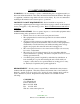
*** SAFETY INFORMATION *** WARNING!!! - Do not attempt to operate or maintain this piece of equipment until you have read and understand all of the safety information included in the manual. This piece of equipment contains moving which can cause serious injury. If you do not understand anything in this manual seek assistance prior to operations.
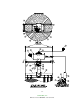
OPERATION PRINCIPLE A. Solids laden air or gases enter the unit at the hopper or housing inlet. B. Air passes through the filter media. C. Solids are retained on the filter media surface. D. Cleaning consists of a rotating pulse arm with nozzles positioned over the bags that randomly pulses 7-8” PSI air into the bags that reverses the airflow. 1. This momentarily takes a row of bags off stream through pressure reversal. 2. Flexing filter bags. 3.
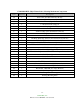
CAMCORP HVP (High Volume Pulse) Cleaning Mechanism Components Item Quantity Description 1A 1B 2 3 4 5 6 7 8 9 10 11 12 13 14 15 16 17 18 19 20 21 22 23 24 25 1 1 1 1 1 1 1 1 1 1 1 1 1 1 2 1 1 1 1 1 1 1 1 1 1 1 Pulse Arm (Size Determined by Model) Pulse Arm (Size Determined by Model) 8” OD Rotary Spool Section 8” OD Arm Rotation Support 8” Diaphragm Valve Solenoid Valve – NEMA 4 or NEMA 9 Tank Assembly (Size Determined by Model) 2” Weighted Relief Valve Solid State Timer PD Pump Discharge Silencer (Size
3-3 CAMCORP, INC.
3-4 CAMCORP, INC.
ON SITE STORAGE RECOMMENDATIONS I. Baghouse and Housing 1. Housing can be stored outside. 2. Equipment must be blocked up to keep the flanges out of the dirt. 3. Many units are supplied with a plain finish bare steel interior. If storage of more than two week is anticipated, the interior should be prime coated before storage. 4. Covering the unit with a tarp is recommended to keep the interior from rusting or corroding as well as keeping the finish in new condition.
ON SITE STORAGE RECOMMENDATIONS (continued) IV. Fan and Fan Accessories 1. Fans can be stored outside on a pallet or skid to keep out of water and dirt. 2. Equipment should be covered with a tarp to protect from the bags. 3. Fan silencers, outlet dampers, and inlet boxes should also be tarped and stored on a pallet or skid. V. Ducting 1. Ducting can be stored outside on a pallet or skid to keep it off the ground. It should be positioned so that water does not sit in the equipment. 2.
ON SITE STORAGE RECOMMENDATIONS (continued) IX. Butterfly (Wafer Valve) 1. All limit switches, solenoids, and air cylinder ports must be capped and taped to prevent any moisture or dirt from entering. 2. Unit can be stored outside provided it is covered with a tarp and is on a pallet or skid to keep it out of the water and dirt and sunlight. X. Level Indicators Store these items inside a cool dry area protected from rodents XI.
SETTING UP YOUR UNIT CAMCORP dust collectors are shipped in various states of assembly depending on the size and configuration of the unit. Before attempting to move the dust collector or any of its sections, review both the certified general assembly drawing supplied with your unit and the rigging and lifting guidelines included in this manual.
Platform Installation: The platform, ladder, handrail, and bracing are to be installed as shown on the special platform detail provided. Use the part ID’s to locate the parts in the proper location. Explosion Vents (where applicable): 1. Figure 6 – The explosion vents are attached with a minimum of standard steel fasteners for shipment. THESE MUST BE REMOVED and the PVC Bolts installed that are included in the shipment. Extreme care should be exercised when installing the PVC Bolts as they are very fragile.
Electrical: A 120-volt, 60-Hertz, 1-Amp circuit is required to operate the dust collector’s Solid State Timer. A 230/460V 3-phase circuit is required to run the Pulse Arm drive motor and the Cleaning Air PD (Positive Displacement) pump motor. Note: The Adjustable Timer needs to be mounting were the Pressure Gauge on the PD Pump is visible. 5-3 CAMCORP, INC.
Gauges: Check the pressure differential gauge to make sure that the high-pressure tap is connected below the tube sheet and the low-pressure tap is connected above the tube sheet. Verify that the gauge have been zeroed prior to connection when it is in its permanent mounting position. Cleaning Air PD Pump: The PD Pump must be install at the base of the filter to accommodate installation of the Air Supply line. Securely anchor in permanent location.
TOP LOAD BAG AND CAGE INSTALLATION 1. Inspect the cage for any signs of damage, warping, bent wires, or missing welds. 2. Inspect the filter bag for any signs of mold, mildew, ripped seams, or holes. 3. Lower the closed end of the bag through the hole in the tube sheet. 4. With your hands, “kidney shape” the snap band bag top in order to fit and align it within the tube sheet hole. 5. Fit the groove of the snap band to the I.D. of the tube sheet hole and allow it to expand and audibly snap into place.
START-UP CHECKLIST 1. Installation Make sure the unit is secured to grade. The ladder(s) and platform(s) must be tightened and set up according to OSHA requirements. Ducting and piping must be secured and routed out of the way of traffic whenever possible to avoid injury. Ducting must also be free of all debris including moisture. 2. Interior of the dirty air plenum A. Make sure that the filter bag assemblies hang straight and the bottoms do not touch each other or any part of the collector interior.
5. Exterior of dust collector A. Access doors, inspection ports, and relief vents should seat effectively to prevent leakage. B. All bolts must be properly tightened. C. Operate any equipment connected to the dust discharge of the dust collector. Check the rotation of any motor driven equipment such as rotary airlocks, horizontal unloading valves, live bottom bin activators, and screw conveyors. Check slide gates and butterfly valves for binding. 6.
START-UP DUST CONTROL SYSTEMS 1. Fan or blower system A. Start the fan or blower and check rotation. B. Check dust pickup points for proper suction; balance airflow in individual ducts. C. Check for air leakage at all flanged connections. 2. Equipment start-up sequence A. Start the pulse arm drive motor (direction of rotation is not critical). B. Start the PD pump motor and check rotation. C. Adjust timer Off-time by watching pressure gauge on PD pump. The pressure in the tank should peak between 7-8 PSI.
H. Observe the manometer or magnahelic differential pressure gauge reading. As the new filter bags become coated with dust, the efficiency of the filtering action increases, and the differential pressure across the filter bags will also increase. Slowly bring the collector to full load and note the final pressure drop across the filter bags. Never allow the pressure drop across the filter bags to exceed 17” w.g. maximum or filter bags may collapse. I.
SHUT-DOWN PROCEDURES 1. Dust control systems Reverse start-up procedure, shut down fan, then after 5 or 10 minute delay, shut down the PD pump and pulse arm drive motor. 2. Pneumatic systems Reverse start-up procedure, shut down fan, then after 5 or 10 minute delay, shut down the reverse air fan and sweep arm drive motor. 9-1 CAMCORP, INC.
TROUBLESHOOTING THE DUST COLLECTOR I. Excessive pressure drop across filter bags The differential pressure gauge or manometer on your dust collector should read 6” w.g. or less. Higher readings and/or steadily increasing readings are an indication that the main airflow through the dust collector may be restricted, and a potential process problem such as poor suction at duct pickup points may exist. In extreme cases (over 17” w.g.) filter bags will be damaged. Check the following: A.
TROUBLESHOOTING THE DUST COLLECTOR (continued) Visually inspect the bags for heavy caking; if caking is evident, see the note below and take the necessary action to clean the bags. Next, measure the main airflow with a pitot tube or equivalent devise and compare with the original volume for which the unit was designed. If the flow is too high, cut back the main fan to prevent a recurrence of the problem. 3.
TROUBLESHOOTING THE DUST COLLECTOR (continued) II. Extremely Low Pressure Drop A. Pressure Gauge Check the differential pressure gauge or manometer and the tubing leading to the dust collector as in I-A of this section. B. Holes in Filter Bags or Bags Incorrectly Installed. Inspect the filter bags for holes, rips, tears, or excessive wear. Make sure that the filter bags were installed correctly according to the “Bag & Cage Installation” section. C.
TROUBLESHOOTING THE DUST COLLECTOR (continued) B. Residual Dust If dust has gotten into the clean air plenum because of a dropped or torn bag, hole in tube sheet, etc., the pulse air may stir up the dust and allow it to escape into the clean air exhaust. Residual dust may also be driven down inside the filter bags by the pulse air; if the filter bags are filled with several inches of dust, clean both the clean air plenum and the filter bags to avoid further problems. V.
TROUBLESHOOTING THE CLEANING MECHANISM 1. Diaphragm Valve – Pulsing Failure. The Diaphragm assembly consists of (3) components. The main diaphragm valve, the secondary diaphragm valve, and the solenoid valve. Troubleshooting recommendations as follows: A. Main Diaphragm and Secondary Diaphragm: 1. Diaphragm Valve Bleeding Air – Disassemble and inspect both diaphragms for ruptured valves or air bleed holes are restricted. (Reference attached manual) Replace with a repair kit if necessary. 2.
3. Positive Displacement (PD) Pump - Following is a list of possible Symptoms and Troubleshooting Solutions.
Symptom Poor Performance Leaking Oil Possible Causes Restricted Inlet Possible Sources Clogged Filter Element Collapsed Inlet Hose Erroneous Pressure Loose Gauge Connection Gauge Movement Damaged Gauge Inaccurately Calibrated Air Leakage Improper Relief Valve Setting Blown Gaskets Loose Piping Joints Insufficient Rotor Speed Wrong Sheave Set Wrong Motor Speed Slipping Belts Excessive Rotor Clearances Abrasive Wear of Rotor Surfaces Rotor “Lag” Timed Failed Oil Seals Foreign Material in Seal Bor
Symptom Overheating Possible Causes Excessive Pressure Ratio Possible Sources Clogged Filter Element Collapsed Inlet Hose Clogged Dust Vent Filter Undersized Dust Vent Filter Clogged Diffusion Pads Wrong Sheave Set Wrong Motor Speed Slipping Belts Insufficient Rotor Speed 4. Pulse Arm Drive – Motor not rotating. A. Remove the motor from the gear drive and check for proper operation. If the motor does not rotate, repair or replace. B.
SAFETY RECOMMENDATIONS Because this unit may be under pressure, do not attempt to open any device doors or panels while fans or blowers are running. If your unit is equipped with a discharge auger or an airlock, be sure chain guards are installed before start-up and servicing is attempted only after electrical power is locked out. While servicing the filter, it is very important that there are no open flames, welding or grinding sparks.
ROUTINE MAINTENANCE A. Inspection Frequency will vary as widely as there are operating conditions. In general proceed as follows: 1. Daily – Check unit differential pressure. 2. Weekly – Verify that the pulse arm drive and PD Pump are operating properly. 3. Monthly – Lubricate fan, rotary valve and screw conveyor. Check seals on latter two for dust loss. 4. Quarterly – On Top Access Units, check for dust accumulation in clean air plenum. B. Repairs 1.
COMPONENT IOM MANUALS MORSE RAIDER WORM GEAR SPEED REDUCER (Maintenance)......................... 1-8 MARTIN TORQUE LIMITER CLUTCH ................................................................... 7-10 AMERICAN CONTROL PRODUCTS TIMER ........................................................ 11-12 DUROFLOW POSITIVE DISPLACEMENT BLOWER (IOM) ............................... 13-48 14-1 CAMCORP, INC.
Emerson Power Transmission FORM P O Box 687 MAYSVILLE, KY 41056 Phone: 800-626-2093 www.emerson-ept.com 8721 March 2003 ® MAINTENANCE INSTRUCTIONS FOR WORM GEAR SPEED REDUCERS Center Distances 1.33, 1.54, 1.75, 2.06, 2.37, 2.62, 3.00, 3.25 3.75, 4.50, 5.16 and 6.
INTRODUCTION The following instructions apply to RAIDER® Worm Gear Speed Reducers. When ordering parts or requesting information be sure to provide all the data stamped on the reducer nameplate. EQUIPMENT REQUIRED In addition to standard Mechanic's tools, the following equipment is required: arbor press, wheel puller, torque wrench, dial indicator, seal driver, bluing, adhesive sealant, snap ring pliers for internal and external rings.
3. High speed shaft (worm shaft) removal: 1.33 C.D. through 3.25 C.D.: C-Flange units Use a small chisel to make a groove in the stamped steel cover opposite the motor flange. Pry off the cover. Remove internal snap ring from housing bore. Remove motor flange. Using a plastic hammer, gently tap on the motor end of the shaft to feed worm shaft assembly through housing and out. 3.75 C.D. through 6.00 C.D.: Remove motor flange. Remove seal cage opposite motor face. Keep shims with seal cage for reassembly.
D. Work seal loose. Be careful to keep all metal or dirt particles from entering unit. Remove old sealing compound from seal seat if it is present. Also remove burrs and sharp edges from shaft. Clean with rag moistened with solvent. Do not use abrasive material on shaft seal contacting surface. E. Protect seal lips when handling; seal leakage will result if these are damaged. If a seal with rubber coating on the outside diameter (O.D.) is used, no sealant is necessary. If no rubber coating is on seal O.D.
Lubricate Bearing Bores of Housing. Sub-assemble the rear bearing onto worm shaft. Lock rear bearing onto shaft with external snap ring. Insert shaft assembly from opposite extension end into housing until bearing is seated against shoulder in bore. Lock shaft assembly in housing bore with internal snap ring. Coat outside diameter of stamped steel endcover with adhesive sealant (except, if end cover is rubber coated DO NOT use sealant) and press into input bore opposite extension, until flush with housing.
4. Seals - To reassemble seals to unit, see Parts Service Steps on Page 3. 5. Motorized Coupling Adapter Reassemble using the original dimensions determined under "General Instructions" on Page 2. 6. Final Inspection A. Turn the gear train by hand as a final check. B. Re-install reducer and accessories. C. Fill reducer with the recommended oil to the appropriate level. See the installation instructions supplied with the reducer. D.
Martin BULLETIN TL-1 SPROCKET & GEAR, INC.
Torque-Limiter Clutches Martin TORQUE-LIMITER Torque-Limiter clutches may be used with a sprocket, gear, sheave, flange or other driven member. It is recommended that the rubbing sides of the driven member be ground to provide a smooth rubbing surface of 65 to 125 micro-inches. See torque rating table on following page. clutch offers thrifty overload protection that’s easy to adjust.
Torque-Limiter Clutches TORQUE-LIMITER CLUTCHES Stock Plate Sprockets with Ground Each assembled unit contains one spring. Higher ratings can be obtained by ordering a second spring to nest in the original one. Bushings need to be ordered separately if required. G E Face and Bored to Fit the B E D C Torque Limiter J L K UNIT TT25 A The rubbing sides of the center member should be ground parallel — 65 to 125 micro-inches.
Coupling Safety WARNING & SAFETY REMINDER Safety must be considered a basic factor in machinery operation at all times. Most accidents are the result of carelessness or negligence. All rotating power transmission products are potentially dangerous and must be guarded by the contractor, installer, purchaser, owner, and user as required by applicable laws, regulations, standards, and good safety practice.
Made-to-Order and Stock Products Screw Conveyor Components and Accessories SCREWS HOT DIPPED GALVANIZED ANGLE FLANGED “U” TROUGH MILD STEEL AND GALVANIZED FORM FLANGED “U” TROUGH MILD STEEL AND GALVANIZED SECTIONAL FLIGHTS MILD STEEL TUBULAR HOUSING MILD STEEL AND GALVANIZED TROUGH ENDS DISCHARGE GATE FLAT RACK AND PINION INLETS AND DISCHARGE SPOUTS MILD STEEL AND GALVANIZED SHAFT SEAL WASTE PACK HELICOID SCREWS RIGHT HAND AND LEFT HAND MILD STEEL AND GALVANIZED ELEVATOR BUCKETS SHAFT SEAL PLATE
Made-to-Order and Stock Products Stock QD V-Belt Sheaves All Steel Stock Sprockets BORED TO SIZE HARDENED TEETH DOUBLE SINGLE HARDEND TEETH SABER TOOTH® HARDENED TEETH QD TRIPLE Stock Bushings/Hubs BUSHINGS TYPE QD STEEL WITH KEYSEAT SIZE SF-N “3V” HI-CAP® “5V” HI-CAP® “8V” HI-CAP Stock Tapered Bushed V-Belt Sheaves TAPERED BUSHING QD IDLER BUDSHING Stock Gears/Steel and Cast CONVENTIONAL C SECTION TAPER BUSHED “3V” HI-CAP® TAPER BUSHED CONVENTIONAL B SECTION TAPER BUSHED Stock Couplings/C
Extensive stockyards of screws are available for quick shipment. A broad inventory of equipment ensures prompt worldwide delivery. Quality material and an experienced staff means a rapid turnaround for you, our customer. SERVICE CENTERS WORLDWIDE USA Mini Manufacturing Centers General Offices Sales and Manufacturing Boston, MA Arlington, TX 3100 Sprocket Drive 76015-2898 P.O.
TIMING MODULE FULLY SOLID STATE ENCAPSULATED ONE AMPERE LOAD RATING E75633 LR46938 Series 606 - PROGRAMMABLE RECYCLE CMOS DIGITAL CIRCUITRY • • • • Life Expectancy –unlimited Environment Protected Tamper Proof No False Operate • • • Small Size – 2"x 2" x 53/64" Lightweight – approximately 2.5 oz. Rugged Application of power simultaneously initiates timing and turns the load ON. The load remains ON for the preset ON time period after which it turns OFF for the preset OFF time period.
CALIBRATION RESISTANCE VS TIME ACCESSORIES – AVAILABLE FROM STOCK ORDER P/N: PM – 1M 1 MEGOHM ± 20% PM – 100K 100 KOHM ± 20% TYPICAL WIRING OUTLINE DRAWING Order bracket mount model as: 606BM – (T1) (T2) (V) (P1) (P2) 606RBM (T1) (T2) (V) (P1) (P2) MADE IN USA AMERICAN CONTROL PRODUCTS A DIV. OF PRECISION TIMER CO., INC. 47 WESTBROOK INDUSTRIAL PARK ROAD WESTBROOK, CT. 06498 PHONE: (860)399-6253 FAX:(860)399-5619 EMAIL:info@precisiontimer.com Web Site: precisiontimer.
PARTS LIST OPERATING AND SERVICE MANUAL SERIES: 30 & 70 BLOWERS Models: GGB_ _B GGG_ _C_ D-- 9-- 610 Version 10 November, 2005
MAINTAIN BLOWER RELIABILITY AND PERFORMANCE WITH GENUINE DUROFLOW PARTS AND SUPPORT SERVICES FROM GARDNER DENVER Factory genuine parts, manufactured to design tolerances, are developed for optimum dependability -----specifically for your blower. Design and material innovations are born from years of experience with hundreds of different blower applications. When you specify factory genuine parts you are assured of receiving parts that incorporate the most current design advancements . . .
GARDNER DENVER LUBRICANT ORDER INFORMATION Re--order Part Numbers for Factory--Recommended Lubricants.
FOREWORD DuroflowR blowers are the result of advanced engineering and skilled manufacturing. To be assured of receiving maximum service from this machine, the owner must exercise care in its operation and maintenance. This book is written to give the operator and maintenance department essential information for day-to-day operation, maintenance and adjustment. Careful adherence to these instructions will result in economical operation and minimum downtime.
SAFETY PRECAUTIONS Safety is everybody’s business and is based on your use of good common sense. All situations or circumstances cannot always be predicted and covered by established rules. Therefore, use your past experience, watch out for safety hazards and be cautious. Some general safety precautions are given below: Failure to observe these notices could result in injury to or death of personnel.
TABLE OF CONTENTS Page Maintain Blower Reliability and Performance with Genuine DuroFlow Parts and Support Services . . . . . . . . . . . . i Remanufactured Blower Program (see page 19 for complete details) . . . . . . . . . . . . . . . . . . . . . . . . . . . . . . . . . . . . . i Gardner Denver Lubricant Order Information . . . . . . . . . . . . . . . . . . . . . . . . . . . . . . . . . . . . . . . . . . . . . . . . . . . . . . . . . . ii Foreword . . . . . . . . . . . . . . . . . . . . . . . . . . . . .
INDEX AEON PD Food Grade Lubricant Part Numbers . 10 Lubrication Service, Air Seal Vent Systems . . . . . 12 AEON PD Lubricant Part Numbers . . . . . . . . . . . . 10 Lubrication Service, Oil Sump Breathing System . 12 Air Seal Vent Systems . . . . . . . . . . . . . . . . . . . . . . . 12 Alignment, Belt Drive . . . . . . . . . . . . . . . . . . . . . . . . . 9 Base and Foundation . . . . . . . . . . . . . . . . . . . . . . . . . 7 MAINTENANCE AND TROUBLESHOOTING, SECTION 5 . . . . . . . . . . . . . .
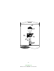
LIST OF ILLUSTRATIONS Figure 1--1 Blower Configuration Changes . . . . . . . . . . . . . . . . . . . . . . . . . . . . . . . . . . . . . . . . . . . . . . . . . . . . . . 4 Figure 1--2 Outline . . . . . . . . . . . . . . . . . . . . . . . . . . . . . . . . . . . . . . . . . . . . . . . . . . . . . . . . . . . . . . . . . . . . . . . . . . . 5 Figure 1--3 Blower Outline Dimension Chart . . . . . . . . . . . . . . . . . . . . . . . . . . . . . . . . . . . . . . . . . . . . . . . . . . . . .
DUROFLOW BLOWERS -- 30 & 70 SERIES MATRIX/MENU NOTICE TO CUSTOMER -- To find the construction options for your blower unit, FILL IN THE BALANCE OF LETTERS OR NUMBERS FROM YOUR UNIT NAMEPLATE COLUMN NUMBER: G __ G __ __ __ __ __ __ __ __ __ __ 1 2 3 4 5 6 7 8 9 10 11 FOLLOW THE LINE DOWN AND OVER FROM EACH SPACE THUS FILLED IN TO FIND THE APPROPRIATE CONSTRUCTION OPTION WITH WHICH YOUR MACHINE IS EQUIPPED. COLUMN 1 -- BASIC DESIGNATOR COLUMN 2 -- PRODUCT FAMILY G.
INTRODUCTION YOUR KEY TO TROUBLE FREE SERVICE Thank you for investing in DuroFlow quality. The DuroFlow reputation for rugged dependability has been earned by over 70 years of service in demanding, industrial operations where downtime cannot be tolerated and efficient blower performance is expected. Your DuroFlow blower is a precision engineered blower that has been carefully manufactured and thoroughly tested at the state-of-the-art Gardner Denver Blower Factory in Sedalia, Missouri.
SECTION 1 GENERAL INFORMATION INSPECTION STORAGE Before uncrating, check the packing slip carefully to be sure all the parts have been received. All accessories are listed as separate items on the packing slip, and small important accessories such as relief valves can be overlooked or lost. After every item on the packing slip has been checked off, uncrate carefully. Register a claim with the carrier for lost or damaged equipment.
VERTICAL TOP ROTATES RIGHT TO BECOME HORIZONTAL RIGHT VERTICAL BOTTOM ROTATES RIGHT TO BECOME HORIZONTAL LEFT VERTICAL TOP ROTATES LEFT TO BECOME HORIZONTAL LEFT VERTICAL BOTTOM ROTATES LEFT TO BECOME HORIZONTAL RIGHT SHAFT ROTATION KEY: NOTE: CW = CLOCKWISE CCW = COUNTERCLOCKWISE When changing configurations be sure to relocate Oil Fill, Oil Drain and Breather Filters into their proper position. 30 Series blowers require a mounting foot change with a configuration change.
D--9--610 Page 5 FIGURE 1-- 2 - OUTLINE
D--9--610 Page 6 3004 16.64 11.62 8.81 2.06 1.000 8.82 12.50 4.00 9.00 4.00 8.06 4.50 6.56 8.36 2--1/2” NPT 1.50 4.41 .53 6.25 2.00 4.50 2.00 3006 18.64 11.62 8.81 2.06 1.000 8.62 12.50 5.50 9.00 5.50 8.06 4.50 6.56 9.36 3” NPT 1.50 4.31 .53 6.25 2.75 4.50 2.75 3.50 9.00 .88 11.00 6.25 7.50 6.25 7009 32.42 23.62 17.25 5.68 2.500 18.00 22.00 12.50 15.00 12.50 15.25 8.25 11.75 17.49 6” NPT 3004 120 3006 135 3.50 9.00 .88 11.00 7.75 7.50 7.75 7012 35.43 23.62 17.25 5.68 2.500 18.00 22.00 15.50 15.
SECTION 2 INSTALLATION LOCATION Whenever possible, install the blower in a clean and dry place that is both well lighted and well ventilated. Provide plenty of room for easy inspection and maintenance. FOUNDATION AND BASE For permanent installations we recommend concrete foundations be provided, and the equipment should be grouted to the concrete. Use non--shrinking grout only.
Series Gear Diameter (Inches) Dimensions (Inches) A B C Maximum Allowable Moment (LB--IN) 30 3 4.75 1.87 .94 1449 70 7 9.45 3.82 .63 14469 MAXIMUM ALLOWABLE MOMENT DRIVE SHAFT ILLUSTRATION Z Ac Z Ac Z Ac Z Ac Z Ac Z Ac 0.000 0.025 0.050 0.075 0.100 0.125 0.150 0.175 0.200 0.225 1.000 0.997 0.994 0.990 0.987 0.983 0.980 0.977 0.973 0.969 0.250 0.275 0.300 0.325 0.350 0.375 0.400 0.425 0.450 0.475 0.966 0.962 0.958 0.954 0.951 0.947 0.943 0.939 0.935 0.930 0.500 0.525 0.
Driver Location -- To properly balance the air load stress on the blower drive shaft, locate the driver on the inlet side for a vertical mounted blower and on the shaft side for a horizontal mounted blower. minimum friction loss. Reducing the pipe diameter on either inlet or discharge will create unwanted restrictions that increase the overall pressure differential and discharge temperature of the blower.
SECTION 3 LUBRICATION All DuroFlow blowers are splash oil lubricated at both the gear and drive ends. Oil is distributed around the gear housing and drive end chamber by the gears and specially designed oil flingers. Approximate oil sump capacities are listed in FIGURE 3--1 below.
Failure to add oil to each end of the blower on 70 series models will result in damage to the blower. The 70 series “C” design version with a column gauge indicates the actual oil level during operation. The column gauge before start--up should be filled to the middle of the glass. The oil level should be maintained at the center of the glass while the blower is not operating. Add fresh oil as required to maintain proper level.
Flush the oil whenever a change is made from one type of oil to another. Flush the oil whenever a change is made from one type of oil to another. Drain the current lubricant as thoroughly as possible. Refill with the new lubricant. Fill to normal level of the blower, which is at the middle of the sight glass when the machine is not operating. Run the blower for one hour. Shut off the blower and drain the lubricant completely. Refill the blower again with the new lubricant.
Blower Discharge Temperature Ambient Temperature Less than10_ F * 10_ F to 32_ F ** 32_ F to 90_ F Less than 32_ F (0_ C) ISO 100 } ISO 100 } 32_ F to 100_ F (0_ C to 38_ C) ISO 100 } ISO 100 } ISO 150 } 100_ F to 225_ F (38_ C to 105_ C) ISO 100 } ISO 100 } ISO 150 } ISO 220 } 225_ F to 300_ F (105_ C to 149_ C) ISO 150 } ISO 150 } ISO 220 } ISO 220 } *** } *** } Greater than 300_ F (149_ C) Greater than 90_ F * For ambient temperatures less than 10_ F, but not less than --20_ F,
SECTION 4 OPERATION Future operating problems can be avoided if proper precautions are observed when the equipment is first put into service. Relief valves should be placed as close as possible to the blower inlet on vacuum systems or discharge on pressure systems. Before starting under power, the blower should be turned over by hand to make certain there is no binding, or internal contact.
MAXIMUM OPERATING LIMITATIONS Size RPM Differential Pressure PSI Dry * Vacuum In HG Discharge Temperature _F 3004 4000 15 15 350 3006 4000 15 15 350 7009 2650 15 15 350 7012 2650 15 15 350 7015 2650 15 15 350 7018 2650 15 15 350 7023 2600 12 16 325 7028 2600 10 16 325 DO NOT EXCEED THESE LIMITS * Increased vacuum levels are attainable with water injection. Contact your DuroFlow Distributor.
BLOWER STARTUP CHECKLIST This startup procedure should be followed during the initial installation and after any shutdown periods or after the blower has been worked on or moved to a new location. It is suggested that the steps be followed in sequence ) in the boxes provided. and checked off ( V V V V V V V V V V V V V V V 1. Check to make certain that the blower has been properly lubricated with AEON PD Synthetic Blower Lubricant. Proper oil level cannot be overemphasized.
SECTION 5 MAINTENANCE AND TROUBLESHOOTING Your DuroFlow blower has been designed, manufactured and tested to precise specifications. Every DuroFlow blower is backed by over 70 years of proven performance in the most demanding applications that modern industry can produce. DuroFlow blowers have been designed specifically for long, trouble--free service. Minimal maintenance is required to keep your DuroFlow blower in top operating condition.
PROBLEM Rotor contact with housing or endplate. Lack of CFM delivery. Excessive bearing or gear wear. Loss of oil from seal vents. Loss of oil from breather filters. Loss of oil from driveshaft seal. Excessive vibration. POSSIBLE CAUSES SOLUTION 1. Insufficient assembled clearances. 1. Return for Warranty. (See page 19.) 2. Case or frame distortion. 2. Remove all mounting and pipe strains. 3. Excessive operating pressure. 3. Remove cause. 4. Excessive operating temperature. 4.
SECTION 6 SERVICE OPTIONS Factory Remanufactured Blower Program STOP incorporates all of the latest design technology and enhancements. You have turned to the service section because you have a blower problem that requires the blower to be mechanically adjusted or repaired. First determine if the blower is still under warranty. Contact your DuroFlow Distributor and provide them with the blower SERIAL NUMBER located on the blower name plate.
advancements . . . manufactured in our state--of--the-art blower factory under exacting quality standards. Parts Ordering Instructions Prepackaged overhaul kits are available for immediate shipment for all DuroFlow blowers. Kits include all the normal wearing parts needed to overhaul your DuroFlow blower: Oil seals, air seals, bearings, spacers, gaskets, and Belleville timing spring. Part numbers for overhaul kits are given below.
SECTION 7 PARTS LISTS AND EXPLODED VIEWS 30 SERIES DUROFLOW BLOWER EXPLODED VIEW 200GGB810 (Ref.
Order by Part Number and Description. Reference Numbers are for your convenience only. Ref. No. Name of Part Qty. Size 3004 GGBA_B_ Part No. Size 3006 GGBB_B_ Part No. DF145949 1 COVER--GEAR . . . . . . . . . . . . . . . . . . . . . . . . . . . . . . . . . . . . . . . . . . . . . 1 DF145949 2 GAUGE--SIGHT . . . . . . . . . . . . . . . . . . . . . . . . . . . . . . . . . . . . . . . . . . . . . 1 40P11 40P11 3 BREATHER . . . . . . . . . . . . . . . . . . . . . . . . . . . . . . . . . . . . .
70 SERIES DUROFLOW BLOWER EXPLODED VIEW 201GGG810--F (Ref.
Order by Part Number and Description. Reference Numbers are for your convenience only. Ref. No. * * * * * * + + *+ * * *++ ** * 1 2 3 4 5 6 7 8 9 10 11 12 13 14 15 16 17 18 19 20 21 22 23 24 25 27 29 30 31 32 33 34 35 36 37 38 39 40 41 42 45 66 67 69 70 * Name of Part Qty. COVER--GEAR . . . . . . . . . . . . . . . . . . . . . . . . . . . . . . . . . . GLASS--SIGHT . . . . . . . . . . . . . . . . . . . . . . . . . . . . . . . . . . SCREW . . . . . . . . . . . . . . . . . . . . . . . . . . . . . . .
Order by Part Number and Description. Reference Numbers are for your convenience only. Ref. No. * * * * * * + + *+ * * *++ ** * Name of Part Qty. Size 7023 GGGE_C_ Part No. Size 7028 GGGF_C_ Part No.
WARRANTY DUROFLOW BLOWERS 30 SERIES 70 SERIES GENERAL PROVISIONS AND LIMITATIONS Gardner Denver (the “Company”) warrants to each original retail purchaser (“Purchaser”) of its new products from the Company or its authorized distributor that such products are, at the time of delivery to the Purchaser, made with good material and workmanship. No warranty is made with respect to: 1. Any product which has been repaired or altered in such a way, in the Company’s judgment, as to affect the product adversely.
Warranty Registration Your DuroFlow blower has been designed and manufactured to provide continuous, trouble--free service, year in and year out. Follow the simple maintenance procedures outlined in this manual and you will be assured of superior blower performance and years of dependable blower life. Please register your DuroFlow Blower with our Factory Service & Warranty Department. Complete the warranty registration information below and fax it to Gardner Denver.
For additional information, contact your local representative or Gardner Denver Compressor Division 1800 Gardner Expressway, Quincy, Illinois 62305 Phone (800) 682-9868 • Fax (217) 221-8780 E-mail: pd.blowers@gardnerdenver.com Visit our web site: www.gardnerdenver.com Sales and Service in all major cities Specifications subject to change without notice © Copyright 2005 Gardner Denver, Inc. Litho in U.S.A.