Installation, Operation, & Maintenance Manual CAMCORP Fabricated Airlocks Square & Round Sizes 8” to 30” Unique Design & Engineering Approaches for Industrial Applications
Safety Recommendations ............................................................................ 1-1 Receiving & Inspection of the Airlock........................................................ 2-1 Storage Recommendations .......................................................................... 2-1 Setting Up Your Airlock.............................................................................. 3-1 Operating Principle ..............................................................................
Section 1 – Safety Recommendations It is the owner’s responsibility to maintain the safety features included with this equipment. The safety features may include, but not necessarily be limited to: guards, access doors and covers, warning decals, caution decals, and advisory decals. Replacement features are available from CAMCORP. Do not attempt to operate this equipment until you have read and understand the contents of this manual.
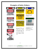
Examples of Safety Stickers DANGER CAUTION OTHER These stickers provide instruction or helpful information. Serial Number Plate The DANGER & CAUTION stickers indicate serious potential hazards which may result in serious injury or possible death. Extreme care should be observed when working in these areas. A tag similar to this will have important information needed by Camcorp when calling for parts or service. 1-2 CAMCORP, INC.
Section 2 - Receiving 0 1 (, 1 2 -* 3 Prior to accepting the shipment(s) care must be taken to inspect all equipment received both for proper count and for damage. Any and all irregularities must be noted on the carrier’s copy of the shipping receipt to assist in settling any claims for damage or shortages. All equipment is shipped FOB point of origin whether on a prepaid or collect freight basis. ANY CLAIM FOR DAMAGE IN TRANSIT OR SHORTAGES MUST BE BROUGHT AGAINST THE CARRIER BY THE PURCHASER.
Section 3 - Installation The shipping cover should be removed from the inlet of the rotary airlock to check for any accessories that were placed inside the airlock for shipment. The inlet and outlet of the airlock should be attached to other components using silicone sealant as a gasket along with the properly sized fasteners. Component flanges must be flat and square.
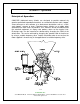
Section 4 – Operation - ,* 6 , -) CAMCORP fabricated rotary airlocks are designed to provide metered dry granular, pelletized or powdered materials at a controlled rate from a bin, hopper, screw conveyor or dust collector to a downstream destination such as a tank, scale hopper, screener or drum. Fabricated rotary airlocks use a rubber wiper attached to the rotor vanes to provide a seal. Some air will be reintroduced into the attached equipment as empty rotor pockets return to the material inlet.
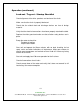
, -) 7 3 . 9 . +8 )1 . )- ., 2 3*( Check alignment of the drive sprockets and tension of the chain. Make sure that the chain is properly lubricated. Check that the airlock feed and discharge devices are free of foreign material. Verify that the electrical connections have been properly attached/installed. Replace the chain guard and make sure that all other safety devices are in place.
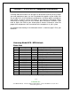
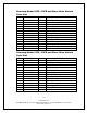
Section 5 – Part Lists & Component Information Camcorp fabricated airlocks are designed to be durable and long lasting. When you need replacement parts use the listing below that applies to your airlock. We are not able to list all of the different configurations and drive options available for each model so please consult the factory if you need this information. When contacting the factory have the serial number plate information available.
)4 -, )- ( ( 4 : 1 2 3 4 5 6 7 8 9 10 11 12 13 14 15 )4 -, 9 9 )4 = ;.) Consult Factory Consult Factory Consult Factory Consult Factory Consult Factory Consult Factory 600026 Consult Factory 600024 / 60030 600003 Consult Factory Consult Factory Consult Factory Consult Factory Consult Factory )4 -, )- ( ( 4 : + * = ) + *)0 &-0 < 9 -, 9 ;.
)4 -, )- ( ( 4 : 1 2 3 4 5 6 7 8 9 10 11 12 13 14 15 )4 -, 9 9 )4 + * = -, 9 ! ;.
)4 -, )- ( ( 4 : 1 2 3 4 5 6 7 8 9 10 11 12 13 14 15 )4 9 -, 9 ;.
)- +. -( Dodge Tigear / Camcorp P/N 600023 Used on Models 8F(S/R) Dodge Tigear / Camcorp P/N 600024 Used on Model 10F(S/R), 12F(S/R) Dodge Tigear / Camcorp P/N 60030 Used on Model 10F(S/R)-S, 12F(S/R)-S, 16F(S/R), 20F(S/R), 24F(S/R) Dodge Tigear / Camcorp P/N 600025 Used on Model 30F(S/R) * - -( Check your specific airlock. Motors sizes range from ½ HP to 5 HP.
Use a No. 2 Lithium complex base grease or equivalent.* Lubrication recommendations are intended for standard products applied in general operating conditions. For modified products, high temperature applications, and other anomalous applications contact product engineering at 864-284-5700 2/05 Use a No. 2 Lithium complex base grease or equivalent.* Lubrication recommendations are intended for standard products applied in general operating conditions.
Section 6 – Troubleshooting - .
Section 7 – Maintenance Check gear reducer oil level monthly. Refer to the general lubrication guidelines in the manufacturer’s insert (manual) accompanying this manual for recommended frequency of oil change and type of oil for the gear reducer.
Section 8 – Drawings On the following pages are shown CAMCORP standard fabricated airlock dimensional drawings. Camcorp can also manufacture these airlocks with special flanges, special materials, special coatings and paint colors, etc. to meet your requirement. Contact a Camcorp representative to discuss your needs. 8-1 9732 Pflumm Road CAMCORP, INC. Lenexa, Kansas 66215 Phone: 913-831-0740 Fax: 913-831-9271 www.camcorpinc.