
Manual

SB-7-
621 Page
32
NOTICE
If gears are being rep
laced, taper pin holes must be drilled after the gears are correctly positioned.
Be careful not to let cuttings drop behind the gears and contaminate the bearings.
Be careful not to let cuttings drop behind the gears and contaminate the bearin
g
s.
F.
Place impellers in the position shown in
FIGURE
7-4
, page
3
0.
Check to be sure impellers
are in correct
position as previously
match marked.
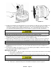
G.
Drive the
mating gear on the other shaft within
1/2” of being flush with the end
of the shaft.
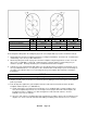
H.
Refer to diagram in
FIGURE 7
-4
, page
30
.
Use feeler gauges to check clearances between
impeller
lobes at
positions
A
--
A and
C
--C. Add the clearances, and divide the total
clearance evenly between A
--
A
and C
--C.
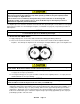
I.
If the lobe clearance is not equal between
A
--
A and C
--C, the impellers require shifting
relative to the
gears. Insert a feeler gauge
.010 inch larger than required clearance between
the impellers at the tight
spot and rotate
the impellers wedging the feeler gauge
between the lobes.
Place the driving tool
against
the gear that is not flush with the end
of the shaft, and strike the driver with a quick
blow.
This will drive
the gear further onto the
shaft, causing it to turn relative to the shaft
due to the torque value set
--
up by the
oversized
feeler gauge wedged between the impeller
lobes.
Adjust so that the clearance at
A
--
A is equal
to C
--
C within .001 inch.
Clearances
must be checked on both sides of
each impeller lobe over the entire
length.
This procedure
may require repeating several
times until the impeller lobe clearance is
equal on
both sides.
NOTICE
The gear used for adjustment should
be flush with its mate on completion
of the timing.
J.
Check gear backlash four places a
t 90 degree
intervals as described in the disassembly
procedure
(Item 4).
NOTICE
If any of the four gear backlash readings are not within the specified limits, the gears must be
replaced.
14.
After timing adjustments are completed,
re
-
ream the origin
al hole between shaft and adjustment gear if
movement between the shaft and gear are negligible. If reaming fails a new hole approximately 90 degrees
from the original hole. Apply a thin coat of Loctite 620 to the taper pin and install the taper pin in
the reamed
hole between the shaft and gear.
NOTICE
Replacement gears are not drilled.
These holes must be drilled after the
gears are in the proper
position and
the unit retimed.
15
.
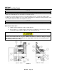
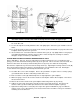
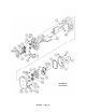
SETTING IMPELLER END CLEARANCES
Refer to FIGURE
7-6
, page 3
3
.
The outer races of
the gear end bearings are clamped against the
headplate
(F) by the bearing retainer (B).
This is referred to as the “fixed end”.
The interference
fit between the shaft and the bearing inner
race
(H)
keeps the shaft from moving axially.
Adjustment is by movement of the shaft through
the gear end bearing
inner race (H).
A.
Check the total end clearance by adding the
clearance between the impellers and the
drive headplate to
the clearance bet
ween
the impellers and the gear headplate.