PRESSURE / VACUUM BLOWER PACKAGE INSTRUCTION, OPERATIONS & MAINTENANCE MANUAL CAMCORP, Inc. Phone: 913-831-0740 ~ Fax: 913-831-9271 www.camcorpinc.
TABLE OF CONTENTS General Information -------------------------------------------------2 Principle of Operation -----------------------------------------------3 Installation ------------------------------------------------------------4 Start-Up------------------------------------------------------------- 5-6 Maintenance ----------------------------------------------------------7 Troubleshooting ------------------------------------------------------8 NOTE: It is the owner’s responsibility to maintain the s
GENERAL COMMENTS: CAMCORP supplies air pump packages comprised of positive displacement blowers manufactured by various companies. A Service Manual for your specific blower is included as an inset in this manual. For specific maintenance and lubrication information, please refer to this insert. -READ & UNDERSTAND SAFETY DECALSInstallation and Operation Cautions: Be sure that the motor is wired for correct rotation; some models of blower are unidirectional and damage could occur if rotation is reversed.
PRINCIPLE OF OPERATION CAMCORP blower packages are set up to provide air to a pressure conveying system or vacuum required for a negative pressure system. Typically the positive displacement blower used on such a package is not capable of supplying air to a pressure higher then 15 psig or vacuum greater then 14” Hg. Depending on the specific blower, it may have a maximum pressure or vacuum capability of somewhat less than that.
INSTALLATION CAMCORP’s positive displacement blower package consists of a positive displacement blower, a vertical or horizontal frame assembly, a motor, take-up table, or motor slide rails, V-belt drive and belt guard, an air intake or inline filter, intake and discharge silencer, a pressure or vacuum relief valve preset at the maximum pressure or vacuum rating of the blower, flexible connections, a check valve (pressure blower assemblies only), pressure/vacuum gauge and pressure or vacuum switch.
LOCKOUT / TAGOUT BEFORE PRE – STARTUP CHECK PRE – START-UP CHECK LIST: A. Check alignment of the drive and tension of the belts. B. Make sure that the blower and all conveying lines are free of foreign material. C. Check pressure relief valve to be sure they are unrestricted. D. Check that the blower has been properly lubricated according to the manufacturers insert. E. Check the breather-filters on the blower for proper installation. F.
E. Check the amp draw of the motor to be sure that the full load amp rating is not exceeded. See motor nameplate. ! Do not operate blower beyond manufacturers recommended limits. ! Be aware that there are also minimum recommended RPM limitations below which adequate lubrication will not be maintained. ! Consult the manufacturers insert or factory for the specific limits for this blower. 6 CAMCORP, Inc. Phone: 913-831-0740 ~ Fax: 913-831-9271 www.camcorpinc.
MAINTENANCE A. Check oil level daily B. Refer to the general lubrication guidelines in this manual for recommended frequency of oil change and type of oil. For more specific information on blower maintenance and lubrication see the manufacturer’s insert (manual) accompanying this manual. C. Clean the intake or inline filter every 40 hours or more often if dust conditions are severe. The filter element is washable using luke warm water with mild detergent. D.
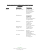
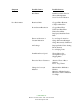
TROUBLESHOOTING POSITIVE DISPLACEMENT ROTARY BLOWERS Symptom Possible Causes Possible Sources Noisiness Rotor-to Rotor Contact Rust Build up or Rotors Rotors Our of Time Excessive Pressure Ratio Failed Bearings (s) Failed Gears Failing Bearing (s) Faulty Installation Non-spec Oil Contaminated Oil Insufficient Oil Improperly Mounted Sheave Over-tightened Belts Failing Gears Insufficient Backlash Non-spec Oil Contaminated Oil Insufficient Oil Sever Torsional Vibration Failing Lubricated Coupling or
Symptom Poor Performance Possible Causes Possible Sources Belt Flutter Insufficient Static Tension Sheave Misalignment Sever Torsional Vibration Restricted Inlet Clogged Filter Element Collapsed Inlet Hose Down Stream Restriction Clogged Dust Filter Undersized Dust Filter Faulty Check Plate Improperly Installed Check Plate Erroneous Pressure or Vacuum Indication Loose Gauge Connection Gauge Movement Damaged Gauge Inaccurately Calibrated Air Leakage Improper Relief Valve Setting Blown Gaskets Lo
Symptom Possible Causes Possible Sources Leaking Oil Failed Oil Seals Foreign Material in Seal Bores Faulty Installation Non-spec Oil Contaminated Oil Overheated Rotor Shafts End Cover Seams Not Tight Bolts Loose Gaskets Torn Oil Foaming Non-spec Oil Oil Cavities Overfilled Excessive Motor Amperage Excessive Pressure Ratio Excessive Pump Speed Line Voltage Drop Air Density Increase Loose Electrical Connections Foreign Material in Air Box Chronic Fuse Blowing or Circuit Breaking Underrated Fuses
Pressure and vacuum switches contain one or two single pole, double throw switches rated (continuous inductive) for 10 amps at 125 or 250 volts or 3 amps at 480 volts. The installation and use of this electrical apparatus must be in accordance with the national electrical code and any other applicable local codes and ordinances. Standard motors supplied by CAMCORP will be 230/460 volt, 3 phase, 60 cycle and control circuits will be 110 volt, single phase, 60 cycle.
l PARTS LIST OPERATING AND SERVICE MANUAL LEGEND “P” SERIES BLOWERS 2” – 5” GEAR DIAMETER Models GAA_ _ P _ GAB_ _ P _ GAC_ _ P _ GAE_ _ P _ SB-7-621 Version 06 April 2, 2007
MAINTAIN BLOWER RELIABILITY AND PERFORMANCE WITH GENUINE GARDNER DENVER PARTS AND SUPPORT SERVICES Factory genuine parts, manufactured to design tolerances, are developed for optimum dependability - - specifically for your blower. Design and material innovations are born from years of experience with hundreds of different blower applications.
GARDNER DENVER LUBRICANT ORDER INFORMATION Re--order Part Numbers for Factory--Recommended Lubricants.
FOREWORD Sutorbilt blowers are the result of advanced engineering and skilled manufacturing. To be assured of receiving maximum service from this machine, the owner must exercise care in its operation and maintenance. This book is written to give the operator and maintenance department essential information for day-to-day operation, maintenance and adjustment. Careful adherence to these instructions will result in economical operation and minimum downtime.
SAFETY PRECAUTIONS Safety is everybody’s business and is based on your use of good common sense. All situations or circumstances cannot always be predicted and covered by established rules. Therefore, use your past experience, watch out for safety hazards and be cautious. Some general safety precautions are given below: Failure to observe these notices could result in injury to or death of personnel. Keep fingers and clothing away from revolving fan, drive coupling, etc.
TABLE OF CONTENTS Maintain Blower Reliability And Performance............................................................................................................ 2 Foreword .................................................................................................................................................................... 4 Safety Precautions..................................................................................................................................................
INDEX Aeon PD Food Grade Lubricant ..................................... 18 Aeon PD Synthetic Lubricant.......................................... 18 Air Filters And Filter Silencers ........................................ 16 Assembly Instructions, Section 7 .................................... 28 Mechanical Seals Only ............................................. 28, 29 Mounting Configurations................................................. 12 Blower Startup Checklist....................................
SUTORBILT LEGEND SERIES BLOWERS MATRIX/MENU NOTICE TO CUSTOMER – To find the construction options for Your blower unit, FILL IN THE BALANCE OF LETTERS OR NUMBERS FROM YOUR UNIT NAMEPLATE COLUMN NUMBER: FOLLOW THE LINE DOWN AND OVER FROM EACH SPACE THUS FILLED IN TO FIND THE APPROPRICATE CONSTRUCTION OPTION WITH WHICH YOUR MACHINE IS EQUIPPED.
INTRODUCTION YOUR KEY TO TROUBLE FREE SERVICE Thank you for investing in Sutorbilt quality. The Sutorbuilt reputation for rugged dependability has been earned by over 50 years of service in demanding, industrial operations where downtime cannot be tolerated and efficient blower performance is expected. Your Sutorbilt blower is a precision engineered blower that has been carefully manufactured and thoroughly tested at the state-of the art Gardner Denver Blower Factory in Sedalia, Missouri.
SECTION 1 EQUIPMENT CHECK Before uncrating, check the packing slip carefully to be sure all the parts have been received. All accessories are listed as separate items on the packing slip, and small important accessories such as relief valves can be overlooked or lost. After every item on the packing slip has been checked off, uncrate carefully. NOTICE Register a claim with the carrier for lost or damaged equipment.
Blower inlet and outlet are temporarily capped to keep out dirt and other contaminants during shipment. These covers must be removed before start-up. The internal surfaces of all Sutorbilt units are mist sprayed with a rust preventative to protect the machine during shipment. Remove this film upon initial startup, using any commercial safety solvent. Position the blower so that the inlet and discharge connections are in the vertical position (vertical airflow).
SECTION 2 INSTALLATION LOCATION Install the blower in a well lit, clean dry place with plenty of room for inspection and maintenance. FOUNDATIONS For permanent installation we recommend concrete foundations be provided, and the equipment should be grouted to the concrete. It is necessary that a suitable base be used, such as a steel combination base under blower and motor, or a separate sole plate under each.
FIGURE 2-1 – BLOWER MOUNTING CONFIGURATIONS 4. Secure the mounting feet capscrews to the torque value in Figure 7-8, page 34. NOTICE When changing mounting configuration, it may be necessary to reposition vent plug (B), and drain plug (A). Refer to Figure 3-1, page 17, for correct location. DRIVE INSTALLATION When selecting a V-belt drive, check to be sure the shaft overhung load limitation is not exceeded. Refer to FIGURE 2-2, page 15, for overhung load calculations and limitations.
Exceeding overhung load limitations leads to unwarrantable premature bearing failure and shaft breakage. The location of the sheave on the blower shaft greatly affects the stress in the shaft. The optimum blower sheave positioning is as close as possible to the blower drive cover, not to exceed dimension “C” in Drive Shaft Illustration, FIGURE 2-2, page 15 The calculated shaft moment must not exceed the maximum allowable moment listed in Maximum Allowable Moment Chart, FIGURE 2-2 page 15.
Dimensions (Inches) B Gear Diameter (Inches) A 2 3 4 5 2.76 2.88 3.49 3.90 .80 .85 1.10 1.40 Maximum Allowable Moment (LB-IN) C (Max) .38 .38 .38 .38 146 385 490 1245 MAXIMUM ALLOWABLE MOMENT DRIVE SHAFT ILLUSTRATION Z Ac Z Ac 0.000 0.025 0.050 0.075 0.100 0.125 0.150 0.175 0.200 0.225 1.000 0.997 0.994 0.990 0.987 0.983 0.980 0.977 0.973 0.969 0.250 0.275 0.300 0.325 0.350 0.375 0.400 0.425 0.450 0.475 0.966 0.962 0.958 0.954 0.951 0.947 0.943 0.939 0.935 0.930 Z 0.500 0.525 0.550 0.
AIR FILTERS AND FILTER SILENCERS Servicing the air filters is one of the most important maintenance operations to be performed to insure long blower life. Servicing frequency of filter elements is not time predictable. A differential pressure indicator, with a continuous gauge reading, should be installed across the inlet filter. It will tell how much of the service life of the filter element has been used.
SECTION 3 LUBRICATION FIGURE 3-1 - LUBRICATION DRIVE END LUBRICATION Drive end bearings are grease lubricated at the factory with Lithium Complex based grease. For relubrication, use Gardner Denver AEON PD Grease, Part Number 28H283. AEON PD Grease is a high temperature, high performance grease that is formulated with antiwear additives to provide superior service under the severe operating conditions of positive displacement blowers.
RECOMMENDED LUBRICANT Gear Diameter 2” 3” 4” 5” Vertical Horizontal 1/4 PT. 1/2 PT. 1/3 PT. 2/3 PT. 3/4 PT. 1 PT. 1 PT. 2-1/4 PT. FIGURE 3-2 – APPROXIMATE OIL CAPACITIES The factory recommended lubricant is AEON PD Synthetic Lubricant. AEON PD is formulated especially for positive displacement blowers to provide maximum protection at any temperature. One filling of AEON PD will last a minimum of 4 times longer than a premium mineral oil, depending on actual operating conditions.
Do not overfill as this will tend to cause excessive heating of the gears and may damage the unit. AEON PD Synthetic Lubricant should be drained after 6000 hours of operation. Re-fill with fresh AEON PD oil. If mineral oil is used, perform the above oil—change maintenance every 1500 hours. Recommended service intervals are for normal blower operating conditions. Severe operating conditions may warrant more frequent oil changes.
SECTION 4 OPERATION Future operating problems can be avoided if proper precautions are observed when the equipment is first put into service. Before starting under power, the blower should be turned over by hand to make certain there is not binding or internal contact. Each size blower has limits on pressure differential, running speed and discharge temperature which must not be exceeded. These limits are shown in “Maximum Operating Limitations”, FIGURE 4-1, below.
BLOWER STARTUP CHECKLIST This startup procedure should be followed during the initial installation and after any shutdown periods or after the blower has been worked on or moved to new location. It is suggested that the steps be followed in sequence and checked off (v) in the boxes provided. 1. Check the unit and all piping for foreign material and clean if required. 2. Check the flatness of the feet and the alignment of the drive.
SAFETY PRECAUTIONS 1. 2. 3. 4. 5. Do not operate blower with open inlet or outlet port. Do not exceed specified vacuum or pressure limitations. Do not operate above or below recommended blower speed range. Blower is not to be used where non-sparking equipment is specified. Do not operate without belt guard or coupling shield. Do not exceed sheave or coupling manufacturer’s rim speed limit. 6. The blower and blower discharge piping may be extremely hot and cause skin burns on contact.
SECTION 5 MAINTENANCE ORDER SPECIAL TOOLS BY PART NUMBER. SEE PAGE 1 FOR ORDERING INSTRUCTIONS.
Unit Size 2” 3” 4” 5” Part Number 204GAA074 205GAA074 206GAA074 207GAA074 FIGURE 5-3 – MECHANICAL SEAL INSTALLATION TOOL Unit Size 2” 3” 4” 5” Part Number 200GAA074 201GAA074 202GAA074 203GAA074 FIGURE 5-4 – BEARING PRESS TOOL – MECHANICAL SEAL UNITS SB-7-621 Page 24
SECTION 6 DISASSEMBLY INSTRUCTIONS NOTICE Numbers in parentheses ( ) refer to key numbers in assembly drawings on pages 35, 37, 39 and 41. 1. Drain oil from gear case by removing drain plug (4). 2. Remove the socket head bolts (5) from the gear cover (3). 3. Remove the gear cover from the gear headplate. NOTICE The cover and gear headplate gasket tends to bond tightly to both surfaces.
FIGURE 6-4 FIGURE 6-3 NOTICE If backlash is above the specified limit, the gears are not necessarily unusable. Excessive play could be caused by worn bearings. 5. to 6. If timing gears appear to be reusable, match marktiming gear toothmesh by making small punch marks on the ends of meshing gear teeth with a pin punch and hammer (see FIGURE 6-2, page 25). The impeller tip valley (throat) and the case to headplates should also be matchmarked to facilitate blower reassembly.
8. Remove mounting foot (17) from the drive headplate (24) by removing the capscrews (16). 9. Remove the capscrews (21) which secure the drive headplate (24) to the impeller case (22). 10. Using the puller plate shown on page 23, bolt to the drive headplate using the tapped holes used to secure the drive cover. 11. Install a gear puller to each shaft and attach puller arms to the plate.
SECTION 7 ASSEMBLY INSTRUCTIONS NOTICE Numbers in parentheses ( ) refer to key numbers in assembly drawings on pages 35, 37, 39 and 41. 1. Make sure all metallic parts are clean and free of any nicks or burrs. 2. Lubricate the outside diameter of the lip seal (15) with a light oil or grease. Install seals in both the drive headplate (24) and gear headplate (18). The seal lip should always face towards the bearing or lubricant. New seals should be installed each time the headplate is removed.
FIGURE 7-3 FIGURE 7-2 3. Assemble gear headplate (18) and mounting foot (17) to the impeller case with cap screws (21) and where the mounting foot is secured to the headplate use capscrews (16). The two positioning dowel pins (19) will ensure proper alignment of the headplate and impeller case. Also secure lifting lugs using capscrews (21) (see exploded assembly drawing on page 35. Refer to Figure 7-8, page 34, for torque specifications.
CLEARANCES FOR STANDARD UNITS ONLY 2M 2L TOTAL END CLEARANCE .006-.009 IMPELLER TO GEAR HEADPLATE .003-.004 IMPELLER TIMING (A-A) (C-C) .005-.008 TIP TO CASE CLEARANCE (B-B) 0.002 min. 3H 3M 3L 0.007-0.011 0.003-0.005 0.005-0.007 .006-.008 0.002 min. 4H 4M 4L 5H 0.007-0.011 .007-.010 5L 0.007-0.011 0.003-0.005 0.006-0.008 5M 0.003-0.005 .007-.010 0.002 min. .008-.010 0.002 min.
These impeller-to-impeller and impeller-to-case clearances are extremely critical. Even though the blower may turn freely by hand when cold, under operating conditions, the parts expand, and the rotors are subject to slight defection. If the clearances are not sufficient, the impellers may contact each other or the housing with destructive results. If the clearances are too great, the blower may not develop the pressure or airflow that is required to perform its function. 12.
NOTICE If gears are being replaced, taper pin holes must be drilled after the gears are correctly positioned. Be careful not to let cuttings drop behind the gears and contaminate the bearings. Be careful not to let cuttings drop behind the gears and contaminate the bearings. F. Place impellers in the position shown in FIGURE 7-4, page 30. Check to be sure impellers are in correct position as previously match marked. G.
FIGURE 7-6 FIGURE 7-7 NOTICE Check the clearance over the entire width of the impeller and consider the tightest spot. B. Divide the total end clearance by 3 and distribute approximately 1/3 on the gear end and the remaining 2/3 on the drive end. C. To move the impeller assembly toward the drive end, lightly tap the shaft at the gear end with a soft face mallet. D.
16. Replace drive shaft grease seal (31) in the drive end cover (29). The seal lip should always face towards the bearing or lubricant. Pack bearing cavities with recommended grease and secure drive cover with capscrews (30) to drive headplate. Refer to FIGURE 7-8 for torque specifications. Exercise care not to damage the seal lip as it passes over the shaft keyway. 17. Assemble the gear cover (3) and gasket (7) to the gear headplate (18) using capscrews (5). Tighten the capscrews alternately and evenly.
SECTION 8 PARTS LIST 300GAA810-C (Ref.
Order by Part Number and Description. Reference Numbers are for your convenience only. Ref. No. O O O + O O 1 2 3 4 5 6 7 8 9 10 12 13 14 15 16 17 18 19 20 21 22 23 24 25 26 27 + 28 29 30 O 31 *+ 42 O O 76 No. Req’d Description NAMEPLATE............................................................... OIL LEVEL PLUG........................................................ GEAR CASE................................................................ DRAIN PLUG..............................................
200GAB810-E (Ref.
Order by Part Number and Description. Reference Numbers are for your convenience only. Ref. No.
300GAC810-B (Ref.
Order by Part Number and Description. Reference Numbers are for your convenience only. Ref. No. O O O + O O 1 2 3 4 5 6 7 8 9 10 12 13 14 15 16 17 18 19 20 21 22 23 24 + O O *+ *+ 25 26 27 28 29 30 31 35 40 42 44 46 O O 76 No. Description Size -- 4H Req’d NAMEPLATE .............................................................................. PLUG FOR ALTERNATE OIL LEVEL CONN. ............................ GEAR CASE ...............................................................................
300GAC810-B (Ref.
Order by Part Number and Description. Reference Numbers are for your convenience only. Ref. No.
SB-7-621 Page 43
For additional information contact your local representative or Gardner Denver, 1800 Gardner Expressway, Quincy, IL 62305 Customer Service Department Telephone: (800) 682-9868 Fax: (217) 221-8780 Sales and Service in all major cities. www.gardnerdenver.com pd.blowers@gardnerdenver.com © 2007 Gardner Denver, Inc. Litho in U.S.A.
This document was created with Win2PDF available at http://www.win2pdf.com. The unregistered version of Win2PDF is for evaluation or non-commercial use only. This page will not be added after purchasing Win2PDF.
Installation & Maintenance Instructions SWITCH UNITS TWO-STAGE FIXED DEADBAND SWITCH UNITS OPEN-FRAME TYPE, GENERAL PURPOSE, OR WATERTIGHT SWITCH ENCLOSURE DESCRIPTION The PC-Series Two-Stage Fixed Deadband Switch Units are used with transducer units to make Tripoint Pressure Switches or Temperature Switches. The switch units are made of aluminum alloy and designed for rugged use. The switch unit may be provided as open-frame type or with a general purpose or watertight enclosure.
Piping/Tubing (Pressure Transducer) INSTALLATION OF TEMPERATURE TRANSDUCERS Adequate support of piping and proper mounting of switch should be made to avoid excessive shock or vibration. To minimize the effect of vibration on a switch, mount perpendicular to vibration. Connect piping or tubing to switch at base of transducer. It is recommended that flexible tubing be used whenever possible. Apply pipe compound sparingly to male pipe threads only.
Adjustment Procedures NORMALLY CLOSED Switch Terminal Test Lamp On-Off Switch Terminal Test Lamp On-Off NC On (Closed Circuit) NO Off (Open Circuit) 2. Apply desired acĆ tuation signal. Then back off signal adjustĆ ing nut until switch actuates. NC Off (Open Circuit) NO On (Closed Circuit) 3. Lower signal to check reactuation signal. NC On (Closed Circuit) NO Off (Open Circuit) 1. Starting with zero signal, connect test lamp to common.
Use 1/4 wrench for adjusting nuts CAUTION Adjusting nut will turn easily until it hits a stop. DO NOT OVERTORQUE left side, low signal setting indicator (indicator set at 75 psig) right side, high signal setting indicator (indicator set at 10 psig) high signal adjusting nut low signal adjusting nut Electrical connections are .