PRESSURE / VACUUM BLOWER PACKAGE INSTRUCTION, OPERATIONS & MAINTENANCE MANUAL CAMCORP, Inc. Phone: 913-831-0740 ~ Fax: 913-831-9271 www.camcorpinc.
TABLE OF CONTENTS General Information -------------------------------------------------2 Principle of Operation -----------------------------------------------3 Installation ------------------------------------------------------------4 Start-Up------------------------------------------------------------- 5-6 Maintenance ----------------------------------------------------------7 Troubleshooting ------------------------------------------------------8 NOTE: It is the owner’s responsibility to maintain the s
GENERAL COMMENTS: CAMCORP supplies air pump packages comprised of positive displacement blowers manufactured by various companies. A Service Manual for your specific blower is included as an inset in this manual. For specific maintenance and lubrication information, please refer to this insert. -READ & UNDERSTAND SAFETY DECALSInstallation and Operation Cautions: Be sure that the motor is wired for correct rotation; some models of blower are unidirectional and damage could occur if rotation is reversed.
PRINCIPLE OF OPERATION CAMCORP blower packages are set up to provide air to a pressure conveying system or vacuum required for a negative pressure system. Typically the positive displacement blower used on such a package is not capable of supplying air to a pressure higher then 15 psig or vacuum greater then 14” Hg. Depending on the specific blower, it may have a maximum pressure or vacuum capability of somewhat less than that.
INSTALLATION CAMCORP’s positive displacement blower package consists of a positive displacement blower, a vertical or horizontal frame assembly, a motor, take-up table, or motor slide rails, V-belt drive and belt guard, an air intake or inline filter, intake and discharge silencer, a pressure or vacuum relief valve preset at the maximum pressure or vacuum rating of the blower, flexible connections, a check valve (pressure blower assemblies only), pressure/vacuum gauge and pressure or vacuum switch.
LOCKOUT / TAGOUT BEFORE PRE – STARTUP CHECK PRE – START-UP CHECK LIST: A. Check alignment of the drive and tension of the belts. B. Make sure that the blower and all conveying lines are free of foreign material. C. Check pressure relief valve to be sure they are unrestricted. D. Check that the blower has been properly lubricated according to the manufacturers insert. E. Check the breather-filters on the blower for proper installation. F.
E. Check the amp draw of the motor to be sure that the full load amp rating is not exceeded. See motor nameplate. ! Do not operate blower beyond manufacturers recommended limits. ! Be aware that there are also minimum recommended RPM limitations below which adequate lubrication will not be maintained. ! Consult the manufacturers insert or factory for the specific limits for this blower. 6 CAMCORP, Inc. Phone: 913-831-0740 ~ Fax: 913-831-9271 www.camcorpinc.
MAINTENANCE A. Check oil level daily B. Refer to the general lubrication guidelines in this manual for recommended frequency of oil change and type of oil. For more specific information on blower maintenance and lubrication see the manufacturer’s insert (manual) accompanying this manual. C. Clean the intake or inline filter every 40 hours or more often if dust conditions are severe. The filter element is washable using luke warm water with mild detergent. D.
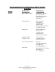
TROUBLESHOOTING POSITIVE DISPLACEMENT ROTARY BLOWERS Symptom Possible Causes Possible Sources Noisiness Rotor-to Rotor Contact Rust Build up or Rotors Rotors Our of Time Excessive Pressure Ratio Failed Bearings (s) Failed Gears Failing Bearing (s) Faulty Installation Non-spec Oil Contaminated Oil Insufficient Oil Improperly Mounted Sheave Over-tightened Belts Failing Gears Insufficient Backlash Non-spec Oil Contaminated Oil Insufficient Oil Sever Torsional Vibration Failing Lubricated Coupling or
Symptom Poor Performance Possible Causes Possible Sources Belt Flutter Insufficient Static Tension Sheave Misalignment Sever Torsional Vibration Restricted Inlet Clogged Filter Element Collapsed Inlet Hose Down Stream Restriction Clogged Dust Filter Undersized Dust Filter Faulty Check Plate Improperly Installed Check Plate Erroneous Pressure or Vacuum Indication Loose Gauge Connection Gauge Movement Damaged Gauge Inaccurately Calibrated Air Leakage Improper Relief Valve Setting Blown Gaskets Lo
Symptom Possible Causes Possible Sources Leaking Oil Failed Oil Seals Foreign Material in Seal Bores Faulty Installation Non-spec Oil Contaminated Oil Overheated Rotor Shafts End Cover Seams Not Tight Bolts Loose Gaskets Torn Oil Foaming Non-spec Oil Oil Cavities Overfilled Excessive Motor Amperage Excessive Pressure Ratio Excessive Pump Speed Line Voltage Drop Air Density Increase Loose Electrical Connections Foreign Material in Air Box Chronic Fuse Blowing or Circuit Breaking Underrated Fuses
Pressure and vacuum switches contain one or two single pole, double throw switches rated (continuous inductive) for 10 amps at 125 or 250 volts or 3 amps at 480 volts. The installation and use of this electrical apparatus must be in accordance with the national electrical code and any other applicable local codes and ordinances. Standard motors supplied by CAMCORP will be 230/460 volt, 3 phase, 60 cycle and control circuits will be 110 volt, single phase, 60 cycle.
ROOTS ® U-RAI rotary positive blowers/exhausters B-12X95 April 2002
Versatile, reliable ROOTSTM Univers Remarkably adaptable You can mount the Universal RAI® blower upside down or rightside up, with vertical or horizontal flow, and with the drive shaft rotating in either direction. With 17 frame sizes to choose from, you have the perfect blower to fit your application with little or no modification. More performance, too Now the Universal RAI® line-up has a broader range and is more rugged than ever, with flows to 2460 CFM, vacuums to 16" Hg and pressures to 15 PSIG.
ersal RAI® blower FITS your application Low cost The ROOTS Universal RAI® line of blowers is designed with the latest engineering technology and built using the most modern manufacturing processes. This results in cost savings we can pass along to you. This genuine ROOTS blower can actually cost less than ordinary competitive units.
You get increased performance through ROOTS’ extensive improvement program and life testing. Here’s how… 1. Exclusive gearbox design “Figure 8” gearbox actually improves oil distribution for longer gear and bearing life with smoother operation. 2. Taper mounted timing gears Carburized and ground alloy steel gears are precision machined and taper fitted to alloy steel shafts, eliminating the need for unreliable timing pins. 3.
5. Versatile mounting 6. Rugged steel mounting feet You can mount the Universal RAI® in multiple positions to accommodate your specific needs. With your choice of 17 frame sizes, there’s a Universal RAI that fits right into your OEM or replacement application. The Universal RAI can be easily changed from horizontal flow to vertical flow using the same mounting feet. They’re even interchangeable with the mounting holes of competitive Roots-type blowers.
Performance Specifications Universal RAI® Pressure Table 2 PSI 4 PSI 5 PSI 6 PSI 7 PSI 10 PSI 11 PSI 12 PSI 13 PSI 14 PSI 15 PSI Frame Speed R P M Size CFM BHP CFM BHP CFM BHP CFM BHP CFM BHP CFM BHP CFM BHP CFM BHP CFM BHP CFM BHP CFM BHP 22 1160 3600 5275 7 46 73 0.3 0.8 1.2 2 41 68 0.4 1.3 1.9 39 66 1.6 2.3 38 64 1.8 2.7 36 63 2.1 3.1 24 1160 19 3600 97 5275 150 0.4 1.3 1.9 11 89 143 0.8 2.3 3.4 8 86 140 0.9 2.8 4.2 83 137 3.3 4.9 81 135 3.8 5.6 32 1160 34 2800 108 3600 144 0.
Universal RAI® Vacuum Table 4" Hg Vacuum CFM BHP 6" Hg Vacuum CFM BHP 8" Hg Vacuum CFM BHP 10" Hg Vacuum CFM BHP 12" Hg Vacuum CFM BHP 14" Hg Vacuum CFM BHP 15" Hg Vacuum CFM BHP 1160 3600 5275 6 45 72 0.3 0.6 1.1 42 69 0.9 1.4 39 66 1.1 1.8 35 62 1.3 2.0 32 59 1.6 2.4 28 55 2.0 2.7 53 3.1 1160 3600 5275 18 96 149 0.3 1.2 1.9 12 90 144 0.6 1.7 2.6 85 139 2.1 3.3 80 134 2.6 3.9 75 128 3.1 4.6 69 122 3.8 5.3 119 5.8 1160 2800 3600 33 107 143 0.5 1.4 1.9 28 102 138 0.
Frame Sizes Frame Size A 22 5.13 5.00 24 5.13 32 B Drive Shaft Location C O O' P P' R U Keyway Inlet & disch. Dia. AX Approx. Net Wt. (lbs.) D D1 D2 9.75 3.75 6.25 3.75 9.63 6.88 6.25 9.25 5.00 .625 .188 x .094 1.0 NPT 1.25 32 7.00 11.75 3.75 6.25 3.75 9.63 6.88 6.25 9.25 5.00 .625 .188 x .094 2.0 NPT 1.25 43 7.25 6.75 11.25 5.00 8.50 5.00 12.81 8.88 7.75 12.13 6.75 .750 .188 x .094 1.25 NPT 1.75 69 33 7.25 7.63 12.13 5.00 8.50 5.
SPECIFICATIONS ROOTSTM Universal RAI Rotary Positive Blowers Frames 22 thru 718 OPERATING PRINCIPLE BASIC BLOWER DESCRIPTION POSITION 1 POSITION 2 POSITION 3 POSITION 4 Two figure-eight lobe impellers mounted on parallel shafts rotate in opposite directions. As each impeller passes the blower inlet, it traps a definite volume of air and carries it around the case to the blower outlet, where the air is discharged.
Dresser, Inc. S-12K84 April 2002 Dresser ROOTS 2135 Hwy 6 South Houston, TX 77077 PH: 281-966-4700 FX: 281-966-4309 Toll Free: 1-877-363-ROOT(S) 2002 Dresser, Inc. ROOTS and Universal RAI are trademarks of Dresser, Inc. All information subject to change without notice. Dresser ROOTS - Connersville 900 West Mount Street Connersville, IN 47331 PH: 765-827-9200 FX: 765-827-9266 Dresser ROOTS, Holmes Operation PO Box B7 Off St.
INSTALLATION OPERATION MAINTENANCE BLOWERS EXHAUSTERS COMPRESSORS ROOTS ™ US $3.00, Canada $4.50 UNIVERSAL RAI & RAM ® ™ SERIES CONTENTS INFORMATION SUMMARY . . . . . . . . . . . 1 TROUBLESHOOTING . . . . . . . . . . . . . . 9 SAFETY PRECAUTIONS . . . . . . . . . . . . 2 MAINTENANCE/REPLACEMENTS OPERATING LIMITATIONS . . . . . . . . . . . 2 UNIVERSAL RAI® SERIES BLOWERS ...........10 RAM™ SERIES BLOWERS .........................14 INSTALLATION . . . . . . . . . . . . . . . . . . . 3 FIGURES .
ROOTS™ products are sold subject to the current General terms of Sale, GTS-5001 and Warranty Policy WP-5020. Copies are available upon request. Contact your local ROOTS Office or ROOTS Customer Service Hot Line 1.877.363.ROOT(S) (7668).
SAFETY PRECAUTIONS It is important that all personnel observe safety precautions to minimize the chances of injury. Among many considerations, the following should be particularly noted: • Blower casing and associated piping or accessories may become hot enough to cause major skin burns on contact. • Internal and external rotating parts of the blower and driving equipment can produce serious physical injuries.
INSTALLATION ROOTS™ blowers & exhausters are treated after factory assembly to protect against normal atmospheric corrosion. The maximum period of internal protection is considered to be one year under average conditions, if shipping plugs & seals are not removed. Protection against chemical or salt water atmosphere is not provided. Avoid opening the unit until ready to start installation, as corrosion protection will be quickly lost due to evaporation.
least 1 inch (25 mm) thick, with its top surface machined flat, and large enough to provide leveling areas at one side and one end after the unit is mounted. It should have properly sized studs or tapped holes located to match the unit foot drilling. Proper use of a high quality machinist’s level is necessary for adequate installation. With the mounting plate in place and leveled, set the unit on it without bolting and check for rocking.
The driver sheave should also be mounted as close to its bearing as possible, and again should fit the shaft correctly. Position the driver on its adjustable base so that 2/3 of the total movement is available in the direction away from the unit, and mount the assembly so that the face of the sheave is accurately in line with the unit sheave. This position minimizes belt wear, and allows sufficient adjustment for both installing and tightening the belts.
LUBRICATION LUBRICATION: For Units with a Grease Lubricated Drive End A simple but very effective lubrication system is employed on the drive shaft end bearings. Hydraulic pressure relief fittings are provided to vent any excess grease, preventing pressure build-up on the seals. A restriction plug and metering orifice prevent loss of lubricant from initial surges in lubricant pressure but permit venting excess lubricant under steadily rising pressures.
OPERATION Before operating a blower under power for the first time, recheck the unit and the installation thoroughly to reduce the likelihood of avoidable troubles. Use the following procedure check list as a guide, but consider any other special conditions in the installation. ❏ Be certain that no bolts, tools, rags, or debris have been left in the blower air chamber or piping.
OPERATING CHARACTERISTICS ROOTS™ rotary blowers and exhausters, as covered in this manual, are available in basic frame sizes ranging from 2 inch to 7 inch gear diameter. Various models, within this gear diameter range, are available with different case lengths to produce reasonable steps in flow capacity. The shorter case lengths have lower volumetric capacities, but are capable of operating against higher pressures.
TROUBLESHOOTING Trouble No flow Item Remedy 1 Speed too low Check by tachometer and compare with published performance 2 Wrong rotation Compare actual rotation with Figure 1 or 2 Change driver if wrong 3 Obstruction in piping Check piping, valves, silencer to assure open flow path 4 Speed too low See item 1, If belt drive, check for slippage and readjust tension 5 Excessive pressure rise Check inlet vacuum and discharge pressure and compare with Published performance 6 Obstruction in pipi
MAINTENANCE & REPLACEMENTS: UNIVERSAL RAI® A good program of consistent inspection and maintenance is the most reliable method of minimizing repairs to a blower. A simple record of services and dates will help keep this work on a regular schedule.
It is recommended that major repairs be performed at an authorized ROOTS facility. However, it is recognized that this may not always be practical. If a blower is out of warranty, mechanical adjustments and parts replacement may be undertaken locally at the owner’s option and risk. It is recommended that ROOTS™ parts be used to insure fit and suitability. The maintenance of a small stock of on-hand spare parts can eliminate possible delays.
6. Check the end clearances between impellers and headplates. Adjust clearances per B-15 below. 7. When clearances are correct, clean and re-install the gearhouse. Check condition of flange gasket (7) and replace if questionable. Fill gearhouse to correct level with proper grade oil. B – Replacing Shaft Bearings and Impellers Remove coupling or sheave from the drive shaft. Drain and remove gearhouse, and pull the timing gears. If gears are to be re-used, mark them so they may be returned to the same shafts.
15. For setting end clearances on 2-1/2” thru 5” gear diameter units, special tools, thrust adjuster fork and thrust adjuster saddle are required. Refer to Table 5 for installation of tools. The flat side of the saddle rests against the bearing inner race and the flat side of the fork rests against the back side of the gear. Install a shim, with thickness equal to gear end clearance (Table 5), between the impeller and the gear end headplates. Tap on top of the fork until the shim becomes snug.
MAINTENANCE & REPLACEMENTS: RAM™ A good program of consistent inspection and maintenance is the most reliable method of minimizing repairs to a blower. A simple record of services and dates will help keep this work on a regular schedule.
It is recommended that major repairs be performed at an authorized ROOTS facility. However, it is recognized that this may not always be practical. If a blower is out of warranty, mechanical adjustments and parts replacement may be undertaken locally at the owner’s option and risk. It is recommended that ROOTS™ parts be used to insure fit and suitability. The maintenance of a small stock of on-hand spare parts can eliminate possible delays.
the headplate bores. Generally, new seals will be required prior to reassembly. 6. Remove the bearing inner race and sleeve (38) from the shaft with the aid of a bearing puller by inserting the puller jaws in the groove in the sleeve and applying the jacking screw against the end of the shaft. Protect the threaded hole and the end of the shaft with a small, flat spacer between the shaft and the puller.
plates to the headplate with capscrews (32) and lock washers (35). 8. Installation of gear end bearings (14) – Turn the blower so that the gear end headplates is up. Heat bearing inner race to 300°F (149°C) in an oven or hot oil; then slide it onto the shaft so that the bearing shoulder is snugly against the sleeve. Insert the bearing outer race and rollers in each bore and tap lightly into place. 9.
FIGURE 2 ALLOWABLE OVERHUNG LOADS FOR V-BELT DRIVES UNIVERSAL RAI® /URAI™ -J UNITS Belt Pull lbs = 252100 • Motor HP Blower RPM • Sheave Diameter C = Distance between drive bearing center line and sheave center line (A+B) B = (1/8” + Sheave Width 2 ) Shaft Load (lb.in) = Belt Pull • C Frame Size A B C Dimension Max Allowable “A” Shaft Load (lb-in.) 22, 24 32, 33, 36 42, 45, 47 53, 56, 59 65, 68, 615 76, 711, 718 0.61 0.80 1.02 1.13 1.36 1.
FIGURE 3 AIR BLOWER INSTALLATION WITH ACCESSORIES Manual Discharge Unloading Valve Back Pressure Regulator (optional) Inlet Air FIlter Pressure Relief Valve Vacuum Relief Valve Check Valve Temperature Gauge Manometers Inlet Silencer Isolation Valve with Limit Switch Temperature Gauge Discharge Silencer Temporary Screen AIR BLOWER Expansion Joint *Differential Pressure & Temperature Switches Expansion Joint with Control Unit Above are suggested locations for available accessories.
FIGURE 4 BLOWER ORIENTATION CONVERSION Model Special Note: WHISPAIR™ models are designed to operate with only one shaft rotation direction to take full advantage of the Whispair feature. Therefore, a WHISPAIR™ blower should be operated in the following combinations only.
FIGURE 5 BLOWER ORIENTATION CONVERSION - WHISPAIR™ UNITS DISCH INLET 1. STANDARD ARRANGEMENT ( 3-WAY UNIVERSAL) EXTERNAL SIGHT GLASSES (37) & BREATHERS (21) MUST BE RELOCATED AS SHOWN. FEET (76&77) & LIFTING LUGS (63) MUST BE RELOCATED AS SHOWN. INLET TOP DRV, L.S. DISCH INLET DISCH DISCH CCW CCW CCW L.H. DRV, BTM DISCH R.H. DRV, TOP DISCH 2. NON-STANDARD ARRANGEMENT ( 3-WAY UNIVERSAL) CYLINDER (11) MUST BE UNBOLTED FROM HEADPLATES (1) AND DISCHARGE RELOCATED AS SHOWN.
TABLE 1 URAI™ -J WHISPAIR™ & URAI™ -G GAS BLOWER, MAXIMUM ALLOWABLE OPERATING CONDITIONS Frame Size 22 24 32 33 36 42 45 47 53 56 59 65 68 615 76 711 718 Gear Diameter (Inch) 2.5 2.5 3.5 3.5 3.5 4.0 4.0 4.0 5.0 5.0 5.0 6.0 6.0 6.0 7.0 7.0 7.0 RAM™ , RAM™ -J WHISPAIR™ Speed RPM 5275 5275 3600 3600 3600 3600 3600 3600 2850 2850 2850 2350 2350 2350 2050 2050 2050 BLOWER, Temp.
TABLE 3 RECOMMENDED OIL GRADES Ambient Temperature °F (°C) Above 90° (32°) 32° to 90° (0° to 32°) 0° to 32° (-18° to 0°) Below 0° (-18°) Viscosity Range SSU at 100°F ISO No. Approximate SAE No. 320 220 150 100 60 50 40 30 1000-1200 700-1000 500-700 300-500 UNIVERSAL RAI® , URAI™ -J, URAI™ -G OIL SUMP CAPACITIES Frame Size 22 24 32 33 36 42 45 47 53 56 59 65 68 615 76 711 718 Capacity Fl. Oz. (Liters) Vertical Horizontal 3.4 (.1) 6.1 (.18) 3.4 (.1) 6.1 (.18) 8.5 (.25) 16.0 (.47) 8.5 (.25) 16.0 (.
TABLE 5 NORMAL CLEARANCES FOR UNIVERSAL RAI® Frame Size 22 24 32 33 36 42 45 47 53 56 59 65 68 615 76 711 718 Total Impeller Ends Drive End Minimum .006/.010 (.15-.25) .006/.010 (.15-.25) .006/.011 (.15-.28) .006/.011 (.15-.28) .006/.011 (.15-.28) .008/.011 (.20-.28) .008/.013 (.20-.33) .008/.013 (.20-.33) .008/.011 (.20-.28) .008/.013 (.20-.33) .008/.013 (.20-.33) .012/.016 (.30-.40) .014/.018 (.36-.46) .014/.018 (.36-.46) .012/.016 (.30-.40) .014/.018 (.36-.46) .014/.018 (.36-.46) .003 (.08) .003 (.
TABLE 6 NORMAL CLEARANCES FOR RAM™ -J & RAM™ -GJ WHISPAIR™ Blower Frame Size 404 406 409 412 418 616 624 Lobes * Impeller at 45° Fronts Min-Max .012-.014 (.31-.36) .012-.014 (.31-.36) .013-.015 (.33-.38) .013-.015 (.33-.38) .013-.015 (.33-.38) .012-.014 (.31-.36) .012-.015 (.31-.36) Backs Min-Max .006-.009 (.15-.23) .006-.009 (.15-.23) .006-.009 (.15-.23) .006-.009 (.15-.23) .006-.009 (.15-.23) .006-.008 (.15-.20) .006-.009 (.15-.
For your nearest ROOTS Office, dial our Customer Service Hot Line 1 877 363 ROOTS (7668). 26 G F E D C B A F:\ 17 FILE\ FORM\ DSIZE.
27 ©2002 Dresser, Inc. all rights reserved. ROOTS, RAM, URAI and WHISPAIR are trademarks of Dresser, Inc. Dresser Design and Universal RAI are registered trademarks of Dresser, Inc. G F E D C B A 0.0000 F:\ 2 SEE NOTE "E" SEE NOTE "D" FORM\ DSIZE.GCM 2 D NUT TO BE TORQUED TO: 6"---400 LB. FT. 7"---550 LB. FT. E FOR SIGHT GLASS UNITS ONLY. USE WASHER OUTSIDE OF GEARBOX. USE RED LOCTITE ON THE THREADS.
For your nearest ROOTS Office, dial our Customer Service Hot Line 1 877 363 ROOTS (7668). G F E D C B A FILE\ FORM\ DSIZE.GCM 0.
29 ©2002 Dresser, Inc. all rights reserved. ROOTS, RAM, URAI and WHISPAIR are trademarks of Dresser, Inc. Dresser Design and Universal RAI are registered trademarks of Dresser, Inc. G F E D C B A 0.0000 F:\ FILE\ A FORM\ DSIZE.GCM 0.1980 1 SEE NOTE "C" 17 9 8 20 3 14 45 44 4 31 2 C NUT TO BE TORQUED TO: 6"---400 LB. FT. B SEE OPERATING MANUAL IRB-180 FOR LUBRICATION INSTRUCTION A USE LOCKTITE #2 (30515) BETWEEN HEADPLATE AND CYLINDER JOINTS.
For your nearest ROOTS Office, dial our Customer Service Hot Line 1 877 363 ROOTS (7668). 30 G F E D C B A 0.0000 F:\ 1 2 FILE\ FORM\ DSIZE.GCM SEE NOTE No.4 400 75 10 3 22 89 28 F 13 1 11 6 22A 12 SEE NOTE No.2 1 16 F 28 89 22 ALSO SHOWN AS GAS SERVICE 1 7 21 90 38 49 22 27 38 8 29 31 2 600 23 4 5 MFG. REF. 600 400 88 32 CONFIDENTIAL SEE NOTE No. 7 SEE NOTE No.5 SEE NOTE No.
UNIVERSAL RAI® Item No. 1 2 3 4 5 7 9 14 15 16 17 19 20 21 23 25 26 27 29 30 31 32 33 34 35 36 37 38 39 40 40* 42 43 44* SERIES BLOWERS PARTS LIST Part Name Headplate Gear End Headplate Drive End Gearbox Gears Cover-Blind (Plug Opening) Gasket Nameplate Lube Bearing G.E., - Driven Bearing Drive D.E.
RAM™ SERIES PARTS LIST Item No. Part Name Qty. 01 03 04 05 07 09 10 14 16 17 19 20 21 22 23 27 28 29 31 32 33 34 35 37 38 38 40 40 42 44 46 49 50 54 60 63 64 66 66.1 70 75 76 77 85 85.1 87 88 90 91 92 93 Headplate Gearbox Gear, Assembly End Cover Gasket – Gearbox/Cover Installation Tag Shims-(.010) Bearing Roller Pin, Dowel (Pull Out) Pin, Dowel Key Square Screw, Drive - Rd. Hd. Breather Plug, Pipe Screw, Cap Hex Hd. Seal, (Viton) Piston, Ring-Seal Washer, Wavy Spring Nut, Hex ESNA Scr, Cap Hex Hd.
NOTES
CONTACT LIST CUSTOMER SERVICE Dresser ROOTS 2135 Hwy 6 South Houston, TX 77077 Toll Free Hot Line: 1-877-363-ROOT(S) (7668) Toll Free Fax: 1-877-357-7238 Local Fax: 281-966-4309 ROOTS Factory Service & Repair Center 11611B Tanner RD Houston, TX 77041 Toll Free: 1-800-866-6182 Local Phone: 713-896-4810 Local Fax: 713-896-4927 Service & Warranty Toll Free: 1-800-866-6182 Local Phone: 832-467-4614 Local Fax: 713-896-4927 Dresser, Inc.
Installation & Maintenance Instructions SWITCH UNITS TWO-STAGE FIXED DEADBAND SWITCH UNITS OPEN-FRAME TYPE, GENERAL PURPOSE, OR WATERTIGHT SWITCH ENCLOSURE DESCRIPTION The PC-Series Two-Stage Fixed Deadband Switch Units are used with transducer units to make Tripoint Pressure Switches or Temperature Switches. The switch units are made of aluminum alloy and designed for rugged use. The switch unit may be provided as open-frame type or with a general purpose or watertight enclosure.
Piping/Tubing (Pressure Transducer) INSTALLATION OF TEMPERATURE TRANSDUCERS Adequate support of piping and proper mounting of switch should be made to avoid excessive shock or vibration. To minimize the effect of vibration on a switch, mount perpendicular to vibration. Connect piping or tubing to switch at base of transducer. It is recommended that flexible tubing be used whenever possible. Apply pipe compound sparingly to male pipe threads only.
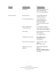
Adjustment Procedures NORMALLY CLOSED Switch Terminal Test Lamp On-Off Switch Terminal Test Lamp On-Off NC On (Closed Circuit) NO Off (Open Circuit) 2. Apply desired acĆ tuation signal. Then back off signal adjustĆ ing nut until switch actuates. NC Off (Open Circuit) NO On (Closed Circuit) 3. Lower signal to check reactuation signal. NC On (Closed Circuit) NO Off (Open Circuit) 1. Starting with zero signal, connect test lamp to common.
Use 1/4 wrench for adjusting nuts CAUTION Adjusting nut will turn easily until it hits a stop. DO NOT OVERTORQUE left side, low signal setting indicator (indicator set at 75 psig) right side, high signal setting indicator (indicator set at 10 psig) high signal adjusting nut low signal adjusting nut Electrical connections are .