PRESSURE / VACUUM BLOWER PACKAGE INSTRUCTION, OPERATIONS & MAINTENANCE MANUAL CAMCORP, Inc. Phone: 913-831-0740 ~ Fax: 913-831-9271 www.camcorpinc.
TABLE OF CONTENTS General Information -------------------------------------------------2 Principle of Operation -----------------------------------------------3 Installation ------------------------------------------------------------4 Start-Up------------------------------------------------------------- 5-6 Maintenance ----------------------------------------------------------7 Troubleshooting ------------------------------------------------------8 NOTE: It is the owner’s responsibility to maintain the s
GENERAL COMMENTS: CAMCORP supplies air pump packages comprised of positive displacement blowers manufactured by various companies. A Service Manual for your specific blower is included as an inset in this manual. For specific maintenance and lubrication information, please refer to this insert. -READ & UNDERSTAND SAFETY DECALSInstallation and Operation Cautions: Be sure that the motor is wired for correct rotation; some models of blower are unidirectional and damage could occur if rotation is reversed.
PRINCIPLE OF OPERATION CAMCORP blower packages are set up to provide air to a pressure conveying system or vacuum required for a negative pressure system. Typically the positive displacement blower used on such a package is not capable of supplying air to a pressure higher then 15 psig or vacuum greater then 14” Hg. Depending on the specific blower, it may have a maximum pressure or vacuum capability of somewhat less than that.
INSTALLATION CAMCORP’s positive displacement blower package consists of a positive displacement blower, a vertical or horizontal frame assembly, a motor, take-up table, or motor slide rails, V-belt drive and belt guard, an air intake or inline filter, intake and discharge silencer, a pressure or vacuum relief valve preset at the maximum pressure or vacuum rating of the blower, flexible connections, a check valve (pressure blower assemblies only), pressure/vacuum gauge and pressure or vacuum switch.
LOCKOUT / TAGOUT BEFORE PRE – STARTUP CHECK PRE – START-UP CHECK LIST: A. Check alignment of the drive and tension of the belts. B. Make sure that the blower and all conveying lines are free of foreign material. C. Check pressure relief valve to be sure they are unrestricted. D. Check that the blower has been properly lubricated according to the manufacturers insert. E. Check the breather-filters on the blower for proper installation. F.
E. Check the amp draw of the motor to be sure that the full load amp rating is not exceeded. See motor nameplate. ! Do not operate blower beyond manufacturers recommended limits. ! Be aware that there are also minimum recommended RPM limitations below which adequate lubrication will not be maintained. ! Consult the manufacturers insert or factory for the specific limits for this blower. 6 CAMCORP, Inc. Phone: 913-831-0740 ~ Fax: 913-831-9271 www.camcorpinc.
MAINTENANCE A. Check oil level daily B. Refer to the general lubrication guidelines in this manual for recommended frequency of oil change and type of oil. For more specific information on blower maintenance and lubrication see the manufacturer’s insert (manual) accompanying this manual. C. Clean the intake or inline filter every 40 hours or more often if dust conditions are severe. The filter element is washable using luke warm water with mild detergent. D.
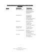
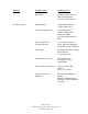
TROUBLESHOOTING POSITIVE DISPLACEMENT ROTARY BLOWERS Symptom Possible Causes Possible Sources Noisiness Rotor-to Rotor Contact Rust Build up or Rotors Rotors Our of Time Excessive Pressure Ratio Failed Bearings (s) Failed Gears Failing Bearing (s) Faulty Installation Non-spec Oil Contaminated Oil Insufficient Oil Improperly Mounted Sheave Over-tightened Belts Failing Gears Insufficient Backlash Non-spec Oil Contaminated Oil Insufficient Oil Sever Torsional Vibration Failing Lubricated Coupling or
Symptom Poor Performance Possible Causes Possible Sources Belt Flutter Insufficient Static Tension Sheave Misalignment Sever Torsional Vibration Restricted Inlet Clogged Filter Element Collapsed Inlet Hose Down Stream Restriction Clogged Dust Filter Undersized Dust Filter Faulty Check Plate Improperly Installed Check Plate Erroneous Pressure or Vacuum Indication Loose Gauge Connection Gauge Movement Damaged Gauge Inaccurately Calibrated Air Leakage Improper Relief Valve Setting Blown Gaskets Lo
Symptom Possible Causes Possible Sources Leaking Oil Failed Oil Seals Foreign Material in Seal Bores Faulty Installation Non-spec Oil Contaminated Oil Overheated Rotor Shafts End Cover Seams Not Tight Bolts Loose Gaskets Torn Oil Foaming Non-spec Oil Oil Cavities Overfilled Excessive Motor Amperage Excessive Pressure Ratio Excessive Pump Speed Line Voltage Drop Air Density Increase Loose Electrical Connections Foreign Material in Air Box Chronic Fuse Blowing or Circuit Breaking Underrated Fuses
Pressure and vacuum switches contain one or two single pole, double throw switches rated (continuous inductive) for 10 amps at 125 or 250 volts or 3 amps at 480 volts. The installation and use of this electrical apparatus must be in accordance with the national electrical code and any other applicable local codes and ordinances. Standard motors supplied by CAMCORP will be 230/460 volt, 3 phase, 60 cycle and control circuits will be 110 volt, single phase, 60 cycle.
Installation & Maintenance Instructions SWITCH UNITS TWO-STAGE FIXED DEADBAND SWITCH UNITS OPEN-FRAME TYPE, GENERAL PURPOSE, OR WATERTIGHT SWITCH ENCLOSURE DESCRIPTION The PC-Series Two-Stage Fixed Deadband Switch Units are used with transducer units to make Tripoint Pressure Switches or Temperature Switches. The switch units are made of aluminum alloy and designed for rugged use. The switch unit may be provided as open-frame type or with a general purpose or watertight enclosure.
Piping/Tubing (Pressure Transducer) INSTALLATION OF TEMPERATURE TRANSDUCERS Adequate support of piping and proper mounting of switch should be made to avoid excessive shock or vibration. To minimize the effect of vibration on a switch, mount perpendicular to vibration. Connect piping or tubing to switch at base of transducer. It is recommended that flexible tubing be used whenever possible. Apply pipe compound sparingly to male pipe threads only.
Adjustment Procedures NORMALLY CLOSED Switch Terminal Test Lamp On-Off Switch Terminal Test Lamp On-Off NC On (Closed Circuit) NO Off (Open Circuit) 2. Apply desired acĆ tuation signal. Then back off signal adjustĆ ing nut until switch actuates. NC Off (Open Circuit) NO On (Closed Circuit) 3. Lower signal to check reactuation signal. NC On (Closed Circuit) NO Off (Open Circuit) 1. Starting with zero signal, connect test lamp to common.
Use 1/4 wrench for adjusting nuts CAUTION Adjusting nut will turn easily until it hits a stop. DO NOT OVERTORQUE left side, low signal setting indicator (indicator set at 75 psig) right side, high signal setting indicator (indicator set at 10 psig) high signal adjusting nut low signal adjusting nut Electrical connections are .