User Manual No. 2 Models: 9710101, 9710102 OUTDOOR PATIO HEATER DANGER FOR YOUR SAFETY If you smell gas: 1. Shut off gas to the appliance. 2. Extinguish any open flames. 3. If odor continues, keep away from the appliance and immediately call your gas supplier or fire department. WARNING Do not store or use gasoline or other flammable vapors and liquids in the vicinity of this or any other appliance. An LP-cylinder not connected for use shall not be stored in the vicinity of this or any other appliance.
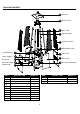
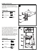
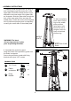
PACKAGE CONTENTS Control Box Assy J Lower Support K Block Belt L Wheel Assembly M Bottom Plate N PART A B C D E F G H I J K DESCRIPTION Reflector Flame Screen Glass Tube Upper Support Protective Guard Black Silicone Ring Side Panel Front Panel Gas Hose & Regulator Control Box Assy Lower Support A Reflector B Flame Screen C Glass Tube D Upper Support E Protective Guard F Black Silicone Ring G Side Panel H Front Panel I QUANTITY 1 1 1 4 4 1 Gas Hose & Regulator PART DESCRIPTION L
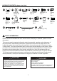
HARDWARE CONTENTS (shown actual size) AA BB Wing nut Qty. 3 GG CC Stud Qty. 3 Small flat washer Φ6 Qty. 6 HH Screw M5 X 12 Qty. 6 NN DD 3/16” Screw Qty. 42 JJ Fixing Bracket Qty. 4 LL Wrench Qty. 1 M6 Flange nut Qty. 4 Bolt M6 X 12 Qty. 4 KK Philips screwdriver Qty. 1 OO Chain Qty.1 FF EE MM Knob Qty. 1 Screw M4 X 10 Qty.1 PP Long Stem Lighter Qty.1 AA Battery (1.5 V) Qty.
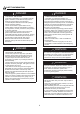
SAFETY INFORMATION DANGER DANGER • EXPLOSION - FIRE HAZARD • Keep solid combustibles, such as building materials, paper or cardboard, a safe distance away from the heater as recommended by the instructions. • Provide adequate clearances around air openings into the combustion chamber. • Never use the heater in spaces that do or may contain volatile or airborne combustibles, or products such as gasoline, solvents, paint thinner, dust particles or unknown chemicals.
SAFETY INFORMATION WARNING WARNING California Proposition 65 Combustion by-products produced when using this product contain chemicals known to the State of California to cause cancer, birth defects, and other reproductive harm. • This product is fueled by propane gas. Propane gas is invisible, odorless, and flammable. An odorant is normally added to help detect leaks and can be described as a “rotten egg” smell. The odorant can fade over time so leaking gas is not always detectable by smell alone.
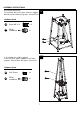
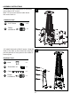
ASSEMBLY INSTRUCTIONS 1. Assemble the wheel assembly to the bottom plate. Fix the wheel assembly to the bottom plate using 4pcs bolt M6X12 and 4pcs flange nut M6. 1 Hardware Used EE Bolt M6 X 12 x4 FF M6 Flange nut x4 JJ Wrench x1 EE M FF 2-1. Unscrew the switch button, load small battery, tighten the switch button. 2-2. Insert the pins of the Bottom Plate to the holes of lower support, press to secure the pins. Using 4pcs screw M5x12 to secure the lower support and Bottom Plate.
ASSEMBLY INSTRUCTIONS 3.Assemble block belt. Fix the block belt to the 2pcs of lower support behind the front door,using 2pcs screw M5X12. 3 Hardware Used GG Screw M5 X 12 KK Philips screwdriver x2 x1 L GG 4 4. Assemble the middle support. Insert the 4pcs upper support to the lower support. Secure them with 8pcs screw 3/16”.
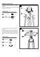
ASSEMBLY INSTRUCTIONS 5. Assebmle the flame screen to the upper support. Secure the flame screen to the upper support using 8pcs 3/16” screw. 5 B Hardware Used DD 3/16” Screw x8 KK Philips screwdriver x1 DD 6. Assemble the reflector onto the flame screen. Screw the 3pcs stud on the flame screen, put 3pcs Φ6 washer onto the top of stud, then put the reflector onto the stud, secure them with 3pcs Φ6 washer and 3pcs wing nut.
ASSEMBLY INSTRUCTIONS 7. Carefully install the glass tube by lifting up and inserting through the center hole in the upper plate. Ensure the black silicone ring is attached to the lower edge of the glass tube as illustrated. Slide the glass tube through the hole of the lower plate cover and onto the middle plate. Check and ensure that the glass tube is positioned properly and is completely covering the center hole of the middle plate.
ASSEMBLY INSTRUCTIONS 9. Attach the three side panels to the heater using 18pcs 3/16” screw. Note : Do not cover the front side where the control knob is. 9 Hardware Used DD 3/16” Screw x 18 KK Philips screwdriver x1 10. Install the knob to M4x10 screw. Hang the chain to the hole on the control box assy and put the pothook of front panel to the holes of bottom plate.
ASSEMBLY INSTRUCTIONS 11. Screw gas hose and regulator to propane cylinder (not included). Do not cross-thread. WARNING: Use a standard 20 lb. propane cylinder only. Use this heater only with a propane vapor withdrawal supply system. See chapter 5 of the standard for storage and handling of liquefied petroleum gas, ANS/NFPA 58. Your local library or fire department should have this book. A minimum supply pressure of 8” W.C. is required for the purpose of input adjustment for propane gas.
ASSEMBLY INSTRUCTIONS WARNING: A dented, rusted or damaged propane cylinder may be hazardous and should be checked by your propane supplier. Never use a propane cylinder with a damaged valve connection. The propane cylinder must be constructed and marked in accordance with the specifications for LP gas cylinders of the U.S. Department of Transportation (DOT) or the standard for cylinders, spheres and tubes for transportation of dangerous goods and commission, CAN/CSA-B339.
OPERATION INSTRUCTIONS Leak Check WARNING • Perform all leak tests outdoors. • Extinguish all open flames. • NEVER leak test when smoking. • Do not use the heater until all connections have been leak tested and do not leak. Hose / Regulator connection Regulator / Cylinder connection 1. Make 2-3 oz. leak check solution (one part liquid dishwashing detergent and three parts water). 2. Apply several drops of solution where hose attaches to regulator. 3.
OPERATION INSTRUCTIONS DANGER • CARBON MONOXIDE HAZARD • For outdoor use only. Never use inside house, or other unventilated or enclosed areas. This heater consumes air (oxygen). Do not use in unventilated or enclosed areas to avoid endangering your life. Caution: Do not attempt to operate until you have read and understand all General Safety Information in this manual and all assembly is complete and leak checks have been performed. Before Turning Gas Supply ON: 1.
OPERATION INSTRUCTIONS 4. Push and release the igniter button until pilot flame is visible through the glass tube. 5. Once the pilot is lit, continue to depress the control knob for 30 seconds. 6. If the pilot does not stay lit, repeat steps 4 to 6. 7. If after repeating steps 4 to 6 unit does not light, then -Push in control knob and turn counterclockwise to “PILOT” (Figure 3). -As you are depressing the control knob, place long stem lighter through the glass tube to light the pilot (Figure 4).
OPERATION INSTRUCTIONS WARNING FOR YOUR SAFETY Be careful when attempting to manually ignite this heater. Holding in the control knob for more than 10 seconds before igniting the gas will cause a ball of flame upon ignition. When heater is ON: Emitter screen will become bright red due to intense heat. The color is more visible at night. Burner will display tongues of blue and yellow flame.
OPERATION INSTRUCTIONS 9. Heater is away from gasoline or other flammable liquids or vapors. 10. Heater is away from windows, air intake openings, sprinklers and other water sources. 11. Heater is at least 2 feet on top and at least 3 feet on sides from combustible materials. 12. Heater is on a hard and level surface. 13. There are no signs of spider or insect nests. 14. All burner passages are clear. 15. All air circulation passages are clear. 16.
CARE AND MAINTENANCE Signs of possible blockage include: Gas odor with extreme yellow tipping of flame. Heater does NOT reach the desired temperature. Heater glow is excessively uneven. Heater makes popping noises. Spiders and insects can nest in burner or orifices. This dangerous condition can damage the heater and render it unsafe for use. Clean burner holes by using a heavy-duty pipe cleaner. Compressed air may help clear away smaller particles. Carbon deposits may create a fire hazard.
TROUBLESHOOTING PROBLEM POSSIBLE CAUSE CORRECTIVE ACTION Cylinder valve is closed Open valve Blockage in orifice or pilot tube Pilot won’t light Air in gas line Note: Heater operates Low gas pressure with cylinder valve fully open at reduced efficiency below 40ºF (5ºC) Igniter fails Pilot won’t stay lit Clean or replace orifice or pilot tube Open gas line and bleed it (pressing control knob in) for no more than 1 - 2 minutes or until you smell gas Turn cylinder valve OFF and replace cylinder Use m
ONE-YEAR LIMITED WARRANTY This product is inspected, tested and carefully packaged to minimize the chance of damage during shipment. If a part within one year from the date of purchase proves to be defective in material or fabrication under normal use, the part will be repaired or replaced. The Company's obligation under the warranty is to replace or repair defective parts at our discretion.
REPLACEMENT PARTS LIST Control Box Assy J Lower Support K Block Belt L Wheel Assembly M Bottom Plate N PART A B C D E F G H I J K DESCRIPTION Reflector Flame Screen Glass Tube Upper Support Protective Guard Black Silicone Ring Side Panel Front Panel Gas Hose & Regulator Control Box Assy Lower Support QUANTITY 1 1 1 4 4 1 3 1 1 1 4 A Reflector B Flame Screen C Glass Tube D Upper Support E Protective Guard F Black Silicone Ring G Side Panel H Front Panel I Gas Hose & Regulator PA