
User Manual

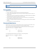
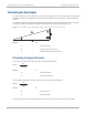


Table Of Contents
- Cambium
- PMP 450 Planning Guide
- Accuracy
- Copyrights
- Restrictions
- License Agreements
- High Risk Materials
- Safety and regulatory information
- Contents
- List of Figures
- List of Tables
- About This Planning Guide
- PMP support website: http://www.cambiumnetworks.com/support
- Cambium main website: http://www.cambiumnetworks.com/
- Sales enquiries: solutions@cambiumnetworks.com
- Email support: support@cambiumnetworks.com
- Cambium Networks
- 3800 Golf Road, Suite 360
- Rolling Meadows, IL 60008
- Chapter 1: Product description
- Chapter 2: Planning considerations
- Regulatory planning
- Network migration planning
- Site planning
- Link planning
- Analyzing the RF Environment
- Selecting Sites for Network Elements
- Diagramming Network Layouts
- Grounding and lightning protection
- Configuration options for TDD synchronization
- Data network planning
- Security planning
- Isolating APs from the Internet
- Managing module access by passwords
- Filtering protocols and ports
- Port Lockdown
- Isolating SMs
- Filtering management through Ethernet
- Allowing management from only specified IP addresses
- Configuring management IP by DHCP
- Planning for airlink security
- Planning for RF Telnet Access Control
- Planning for RADIUS integration
- Planning for SNMP security
- Ordering components
- Chapter 3: Legal information
- Cambium Networks end user license agreement
- Acceptance of this agreement
- Definitions
- Grant of license
- Conditions of use
- Title and restrictions
- Confidentiality
- Right to use Cambium’s name
- Transfer
- Updates
- Maintenance
- Disclaimer
- Limitation of liability
- U.S. government
- Term of license
- Governing law
- Assignment
- Survival of provisions
- Entire agreement
- Third party software
- Hardware warranty
- Limit of liability
- Cambium Networks end user license agreement
- Chapter 4: Reference information

Selecting Sites for Network Elements Planning considerations
2-28
pmp-0047 (December 2012)
Calculating the Aim Angles
The proper angle of tilt can be calculated as a factor of both the difference in elevation and the distance that the link
spans. Even in this case, a plumb line and a protractor can be helpful to ensure the proper tilt. This tilt is typically
minimal.
The number of degrees to offset (from vertical) the mounting hardware leg of the support tube is equal to the angle
of elevation from the lower module to the higher module (<B in the example provided in Figure 15).
Figure 15 Variables for calculating angle of elevation (and depression)
Where:
Is:
b angle of elevation
B vertical difference in elevation
A horizontal distance between modules
Calculating the Angle of Elevation
To use metric units to find the angle of elevation, use the following formula:
Where:
Is:
B expressed in meters
A expressed in kilometers
To use English standard units to find the angle of elevation, use the following formula:
Where:
Is:
B expressed in feet
A expressed in miles
The angle of depression from the higher module is identical to the angle of elevation from the lower module.
tan b =
B
1000A
tan b =
B
5280A