
User Manual
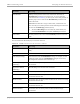


Table Of Contents
- Cambium
- PMP 450 Planning Guide
- Accuracy
- Copyrights
- Restrictions
- License Agreements
- High Risk Materials
- Safety and regulatory information
- Contents
- List of Figures
- List of Tables
- About This Planning Guide
- PMP support website: http://www.cambiumnetworks.com/support
- Cambium main website: http://www.cambiumnetworks.com/
- Sales enquiries: solutions@cambiumnetworks.com
- Email support: support@cambiumnetworks.com
- Cambium Networks
- 3800 Golf Road, Suite 360
- Rolling Meadows, IL 60008
- Chapter 1: Product description
- Chapter 2: Planning considerations
- Regulatory planning
- Network migration planning
- Site planning
- Link planning
- Analyzing the RF Environment
- Selecting Sites for Network Elements
- Diagramming Network Layouts
- Grounding and lightning protection
- Configuration options for TDD synchronization
- Data network planning
- Security planning
- Isolating APs from the Internet
- Managing module access by passwords
- Filtering protocols and ports
- Port Lockdown
- Isolating SMs
- Filtering management through Ethernet
- Allowing management from only specified IP addresses
- Configuring management IP by DHCP
- Planning for airlink security
- Planning for RF Telnet Access Control
- Planning for RADIUS integration
- Planning for SNMP security
- Ordering components
- Chapter 3: Legal information
- Cambium Networks end user license agreement
- Acceptance of this agreement
- Definitions
- Grant of license
- Conditions of use
- Title and restrictions
- Confidentiality
- Right to use Cambium’s name
- Transfer
- Updates
- Maintenance
- Disclaimer
- Limitation of liability
- U.S. government
- Term of license
- Governing law
- Assignment
- Survival of provisions
- Entire agreement
- Third party software
- Hardware warranty
- Limit of liability
- Cambium Networks end user license agreement
- Chapter 4: Reference information

PMP 450 Planning Guide Analyzing the RF Environment
pmp-0047 (December 2012)
2-25
Attribute Meaning
Downlink Data Initially set this parameter to the same value that the AP has for its
Downlink Data parameter (percentage). Then, as you use the Frame
Calculator tool in Procedure 4, you will vary the value in this parameter to
find the proper value to write into the Downlink Data parameter of all
APs in the cluster.
PMP 450 Series APs offer a range of 15% to 85%, and default to 75%.
The value that you set in this parameter has the following interaction with
the value of the Max Range parameter (above):
• The default Max Range value is 5 miles and, at that distance, the
maximum Downlink Data value (85% in PMP450) is functional.
Control Slots Set this parameter to the value of the Control Slot parameter is set in the
APs.
The Calculated Frame Results display several items of interest:
Table 20 OFDM Calculated Frame Results attributes
Attribute Meaning
Modulation The type of radio modulation used in the calculation (OFDM for PMP
450)
Total Frame Bits The total number of bits used in the calculated frames
Data Slots (Down/Up) This field is based on the Downlink Data setting. For example, a result
within the typical range for a Downlink Data setting of 75% is 61/21,
meaning 61 data slots down and 21 data slots up.
Round Trip Air Delay
(MaxRange)
This is the roundtrip air delay in bit times for the Max Range value set in
the calculator
Approximate distance
(MaxRange)
The Max Range value used for frame calculation
AP Transmit End In bit times, this is the frame position at which the AP ceases transmission.
AP Receive Start In bit times, this is the frame position at which the AP is ready to receive
transmission from the SM.
AP Receive End In bit times, this is the frame position at which the AP will cease receiving
transmission from the SM.
SM Receive End In bit times, this is the frame position at which the SM will cease receiving
transmission from the AP.
SM Transmit Start In bit times, this is the frame position at which the SM will begin
transmission.