
User Manual


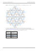


Table Of Contents
- Cambium
- PMP 450 Planning Guide
- Accuracy
- Copyrights
- Restrictions
- License Agreements
- High Risk Materials
- Safety and regulatory information
- Contents
- List of Figures
- List of Tables
- About This Planning Guide
- PMP support website: http://www.cambiumnetworks.com/support
- Cambium main website: http://www.cambiumnetworks.com/
- Sales enquiries: solutions@cambiumnetworks.com
- Email support: support@cambiumnetworks.com
- Cambium Networks
- 3800 Golf Road, Suite 360
- Rolling Meadows, IL 60008
- Chapter 1: Product description
- Chapter 2: Planning considerations
- Regulatory planning
- Network migration planning
- Site planning
- Link planning
- Analyzing the RF Environment
- Selecting Sites for Network Elements
- Diagramming Network Layouts
- Grounding and lightning protection
- Configuration options for TDD synchronization
- Data network planning
- Security planning
- Isolating APs from the Internet
- Managing module access by passwords
- Filtering protocols and ports
- Port Lockdown
- Isolating SMs
- Filtering management through Ethernet
- Allowing management from only specified IP addresses
- Configuring management IP by DHCP
- Planning for airlink security
- Planning for RF Telnet Access Control
- Planning for RADIUS integration
- Planning for SNMP security
- Ordering components
- Chapter 3: Legal information
- Cambium Networks end user license agreement
- Acceptance of this agreement
- Definitions
- Grant of license
- Conditions of use
- Title and restrictions
- Confidentiality
- Right to use Cambium’s name
- Transfer
- Updates
- Maintenance
- Disclaimer
- Limitation of liability
- U.S. government
- Term of license
- Governing law
- Assignment
- Survival of provisions
- Entire agreement
- Third party software
- Hardware warranty
- Limit of liability
- Cambium Networks end user license agreement
- Chapter 4: Reference information

PMP 450 Planning Guide Link planning
pmp-0047 (December 2012)
2-17
Allowed EIRP (dBm) the EIRP limit allowed by the regulations,
Antenna Gain (dBi) the gain of the chosen antenna,
Cable Loss (dB) the loss of the RF cable connecting the AP to the
antenna.
For more information on EIRP limits, see Compliance with radio regulations on page 4-13.
.
Understanding Attenuation
An RF signal in space is attenuated by atmospheric and other effects as a function of the distance from the initial
transmission point. The further a reception point is placed from the transmission point, the weaker is the received
RF signal.
Calculating Link Loss
The link loss is the total attenuation of the wireless signal between two point-to-multipoint units. The link loss
calculation is presented below:
Link Loss (dB) = Transmit power of the remote wireless unit (dBm) − Tx Cable loss (dB) − Received power
at the local unit (dBm) – Rx cable loss (dB) + Antenna gain at the remote unit (dBi) + Antenna gain at the
local unit (dBi)
Calculating Rx Signal Level
The Rx sensitivity of each module is provided at http://www.cambiumnetworks.com. The determinants in Rx signal
level are illustrated in Figure 11.
Figure 11 Determinants in Rx signal level
Rx signal level is calculated as follows: