
User Manual


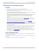


Table Of Contents
- Cambium
- PMP 450 Planning Guide
- Accuracy
- Copyrights
- Restrictions
- License Agreements
- High Risk Materials
- Safety and regulatory information
- Contents
- List of Figures
- List of Tables
- About This Planning Guide
- PMP support website: http://www.cambiumnetworks.com/support
- Cambium main website: http://www.cambiumnetworks.com/
- Sales enquiries: solutions@cambiumnetworks.com
- Email support: support@cambiumnetworks.com
- Cambium Networks
- 3800 Golf Road, Suite 360
- Rolling Meadows, IL 60008
- Chapter 1: Product description
- Chapter 2: Planning considerations
- Regulatory planning
- Network migration planning
- Site planning
- Link planning
- Analyzing the RF Environment
- Selecting Sites for Network Elements
- Diagramming Network Layouts
- Grounding and lightning protection
- Configuration options for TDD synchronization
- Data network planning
- Security planning
- Isolating APs from the Internet
- Managing module access by passwords
- Filtering protocols and ports
- Port Lockdown
- Isolating SMs
- Filtering management through Ethernet
- Allowing management from only specified IP addresses
- Configuring management IP by DHCP
- Planning for airlink security
- Planning for RF Telnet Access Control
- Planning for RADIUS integration
- Planning for SNMP security
- Ordering components
- Chapter 3: Legal information
- Cambium Networks end user license agreement
- Acceptance of this agreement
- Definitions
- Grant of license
- Conditions of use
- Title and restrictions
- Confidentiality
- Right to use Cambium’s name
- Transfer
- Updates
- Maintenance
- Disclaimer
- Limitation of liability
- U.S. government
- Term of license
- Governing law
- Assignment
- Survival of provisions
- Entire agreement
- Third party software
- Hardware warranty
- Limit of liability
- Cambium Networks end user license agreement
- Chapter 4: Reference information

PMP 450 Planning Guide Compliance with safety standards
pmp-0047 (December 2012)
4-11
Calculation of power density
The following calculation is based on the ANSI IEEE C95.1-1991 method, as that provides a worst case analysis.
Details of the assessment to EN50383:2002 can be provided, if required.
Peak power density in the far field of a radio frequency point source is calculated as follows:
Where:
Is:
S power density in W/m
2
P maximum average transmit power capability
of the radio, in W
G total Tx gain as a factor, converted from dB
d distance from point source, in m
Rearranging terms to solve for distance yields:
Calculated distances and power compliance margins
Table 35 shows calculated minimum separation distances, recommended distances and resulting margins for each
frequency band and antenna combination. These are conservative distances that include compliance margins. At
these and greater separation distances, the power density from the RF field is below generally accepted limits for
the general population.
PMP 450 equipment adheres to all applicable EIRP limits for transmit power when operating in MIMO mode.
Separation distances and compliance margins include compensation for both transmitters.
Explanation of terms used in Table 35:
Tx burst – maximum average transmit power in burst (Watt)
P – maximum average transmit power capability of the radio (Watt) (combined transmitters)
G – total transmit gain as a factor, converted from dB
S – power density (W/m
2
)
d – minimum distance from point source (meters)
R – recommended distances (meters)
C – compliance factor
2
4
.
d
GP
S
π
=
S
GP
d
.4
.
π
=