
User Guide
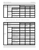
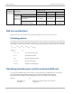
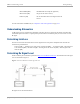
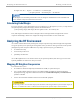
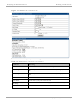
Table Of Contents
- Cambium
- PMP 450 Planning Guide
- Accuracy
- Copyrights
- Restrictions
- License Agreements
- High Risk Materials
- Safety and regulatory information
- Contents
- List of Figures
- List of Tables
- About This Planning Guide
- PMP support website: http://www.cambiumnetworks.com/support
- Cambium main website: http://www.cambiumnetworks.com/
- Sales enquiries: solutions@cambiumnetworks.com
- Email support: support@cambiumnetworks.com
- Cambium Networks
- 3800 Golf Road, Suite 360
- Rolling Meadows, IL 60008
- Chapter 1: Product description
- Chapter 2: Planning considerations
- Regulatory planning
- Network migration planning
- Site planning
- Link planning
- Analyzing the RF Environment
- Selecting Sites for Network Elements
- Diagramming Network Layouts
- Grounding and lightning protection
- Configuration options for TDD synchronization
- Data network planning
- Security planning
- Isolating APs from the Internet
- Managing module access by passwords
- Filtering protocols and ports
- Port Lockdown
- Isolating SMs
- Filtering management through Ethernet
- Allowing management from only specified IP addresses
- Configuring management IP by DHCP
- Planning for airlink security
- Planning for RF Telnet Access Control
- Planning for RADIUS integration
- Planning for SNMP security
- Ordering components
- Chapter 3: Legal information
- Cambium Networks end user license agreement
- Acceptance of this agreement
- Definitions
- Grant of license
- Conditions of use
- Title and restrictions
- Confidentiality
- Right to use Cambium’s name
- Transfer
- Updates
- Maintenance
- Disclaimer
- Limitation of liability
- U.S. government
- Term of license
- Governing law
- Assignment
- Survival of provisions
- Entire agreement
- Third party software
- Hardware warranty
- Limit of liability
- Cambium Networks end user license agreement
- Chapter 4: Reference information

Link planning Planning considerations
2-16
pmp-0047 (December 2012)
Product Parameter
Range Details
2x 4x 6x
Max. NLOS2
Link Budget
(additional 25
dB link loss)
km
with LENS that adds 5.5 dB
to SM Range 1 mi / 1.6 km 0.4 mi / 0.6 km 0.1 mi / 0.2 km
with Reflector Dish that
adds 14 dB to SM Range 2.7 mi / 4.3 km 1 mi / 1.7 km 0.4 mi / 0.6 km
Path loss considerations
Path loss is the amount of attenuation the radio signal undergoes between the two ends of the link.
Calculating path loss
The path loss is the sum of the attenuation of the path if there were no obstacles in the way (Free Space Path Loss),
the attenuation caused by obstacles (Excess Path Loss) and a margin to allow for possible fading of the radio signal
(Fade Margin). The following calculation needs to be performed to judge whether a particular link can be installed:
capabilityseasonal
fadeexcessspacefree
LLLLL <+++
_
Where: Is:
spacefree
L
_
Free Space Path Loss (dB)
excess
L
Excess Path Loss (dB)
fade
L
Fade Margin Required (dB)
seasonal
L
Seasonal Fading (dB)
capability
L
Equipment Capability (dB)
Calculating maximum power level for connectorized AP units
If a connectorized PMP 450 AP is to be installed in a country that imposes an EIRP limit in the selected band,
calculate the highest setting of Maximum Power Level that will be permitted using this formula:
Maximum Power Level (dBm) = Allowed EIRP (dBm) – Antenna Gain (dBi) + Cable Loss (dB)
Where:
Is:
Maximum Power
Level (dBm)
the highest permissible setting of the transmitter
output power,