
User Guide
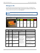
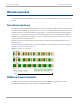
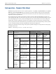
Table Of Contents
- Cambium
- PMP 450 Planning Guide
- Accuracy
- Copyrights
- Restrictions
- License Agreements
- High Risk Materials
- Safety and regulatory information
- Contents
- List of Figures
- List of Tables
- About This Planning Guide
- PMP support website: http://www.cambiumnetworks.com/support
- Cambium main website: http://www.cambiumnetworks.com/
- Sales enquiries: solutions@cambiumnetworks.com
- Email support: support@cambiumnetworks.com
- Cambium Networks
- 3800 Golf Road, Suite 360
- Rolling Meadows, IL 60008
- Chapter 1: Product description
- Chapter 2: Planning considerations
- Regulatory planning
- Network migration planning
- Site planning
- Link planning
- Analyzing the RF Environment
- Selecting Sites for Network Elements
- Diagramming Network Layouts
- Grounding and lightning protection
- Configuration options for TDD synchronization
- Data network planning
- Security planning
- Isolating APs from the Internet
- Managing module access by passwords
- Filtering protocols and ports
- Port Lockdown
- Isolating SMs
- Filtering management through Ethernet
- Allowing management from only specified IP addresses
- Configuring management IP by DHCP
- Planning for airlink security
- Planning for RF Telnet Access Control
- Planning for RADIUS integration
- Planning for SNMP security
- Ordering components
- Chapter 3: Legal information
- Cambium Networks end user license agreement
- Acceptance of this agreement
- Definitions
- Grant of license
- Conditions of use
- Title and restrictions
- Confidentiality
- Right to use Cambium’s name
- Transfer
- Updates
- Maintenance
- Disclaimer
- Limitation of liability
- U.S. government
- Term of license
- Governing law
- Assignment
- Survival of provisions
- Entire agreement
- Third party software
- Hardware warranty
- Limit of liability
- Cambium Networks end user license agreement
- Chapter 4: Reference information

Subscriber Module (SM) Product description
1-12
pmp-0047 (December 2012)
Status information provided
LED Color
when
active
SM in
“Operating”
Mode
SM in “Aiming”
Mode
Notes
SYN/1 yellow
Medium Receive
Signal Power
Blinking from slow to full-on to
indicate medium power, getting
stronger.
PWR red
Registration Indicator
Off when registered to AP.
On when not registered to AP.
Mounting brackets
For mounting PMP 450 SMs, Cambium Networks offers the SMMB1A mounting bracket.
Network connection
The network connection to a PMP 450 Series SM is made via a 100 BaseT Ethernet connection. Power is provided
to the SM over the Ethernet connection using a patented non-standard powering technique.
SM power supply
The SM power supply generates the SM supply voltage (29 VDC) from the external DC source and injects the
supply voltage into the SM.
The power supply is connected to the SM and network equipment using Cat5e cable with RJ45 connectors. Refer
to Cabling and lightning protection on page 1-13.
Further reading on the SM
For more information on the SM, refer to the following:
• AP or SM site selection on page 2-11 describes how to select a site for the SM.