
User Guide
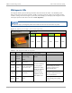
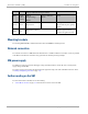
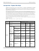
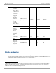
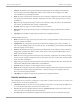
Table Of Contents
- Cambium
- PMP 450 Planning Guide
- Accuracy
- Copyrights
- Restrictions
- License Agreements
- High Risk Materials
- Safety and regulatory information
- Contents
- List of Figures
- List of Tables
- About This Planning Guide
- PMP support website: http://www.cambiumnetworks.com/support
- Cambium main website: http://www.cambiumnetworks.com/
- Sales enquiries: solutions@cambiumnetworks.com
- Email support: support@cambiumnetworks.com
- Cambium Networks
- 3800 Golf Road, Suite 360
- Rolling Meadows, IL 60008
- Chapter 1: Product description
- Chapter 2: Planning considerations
- Regulatory planning
- Network migration planning
- Site planning
- Link planning
- Analyzing the RF Environment
- Selecting Sites for Network Elements
- Diagramming Network Layouts
- Grounding and lightning protection
- Configuration options for TDD synchronization
- Data network planning
- Security planning
- Isolating APs from the Internet
- Managing module access by passwords
- Filtering protocols and ports
- Port Lockdown
- Isolating SMs
- Filtering management through Ethernet
- Allowing management from only specified IP addresses
- Configuring management IP by DHCP
- Planning for airlink security
- Planning for RF Telnet Access Control
- Planning for RADIUS integration
- Planning for SNMP security
- Ordering components
- Chapter 3: Legal information
- Cambium Networks end user license agreement
- Acceptance of this agreement
- Definitions
- Grant of license
- Conditions of use
- Title and restrictions
- Confidentiality
- Right to use Cambium’s name
- Transfer
- Updates
- Maintenance
- Disclaimer
- Limitation of liability
- U.S. government
- Term of license
- Governing law
- Assignment
- Survival of provisions
- Entire agreement
- Third party software
- Hardware warranty
- Limit of liability
- Cambium Networks end user license agreement
- Chapter 4: Reference information

PMP 450 Planning Guide Subscriber Module (SM)
pmp-0047 (December 2012)
1-11
SM diagnostic LEDs
The diagnostic LEDs report the following information about the status of the module. The SM LEDs provide
different status based on the mode of the SM. An SM in “operating” mode will register and pass traffic normally.
An SM in “aiming” mode will not register or pass traffic, but will display (via LED panel) the strength of received
radio signals (based on radio channel selected via Tools, Alignment).
The LED color helps you distinguish position of the LED. The LED color does not indicate any status.
Figure 8 SM diagnostic LEDs, viewed from unit front
SM LED Display LED Labels
LNK/5 ACT/4 GPS/3 SES/2 SYN/1 PWR
Table 5 SM diagnostic LED descriptions
Status information provided
LED Color
when
active
SM in
“Operating”
Mode
SM in “Aiming”
Mode
Notes
LNK/5 green
Ethernet link
These five LEDs act
as a bar graph to
indicate the relative
quality of alignment.
As power level
improves during
alignment, more of
these LEDs are lit.
Continuously lit when link is
present.
ACT/4 yellow
Presence of data activity
on the Ethernet link
Flashes during data transfer.
Frequency of flash is not a
diagnostic indication.
GPS/3 red Interference
On - high interference.
Blinking - medium interference.
Off - low interference.
SES/2 green
Strong Receive Signal
Power
Blinking from slow to full-on to
indicate strong power, getting
stronger.