
User Guide
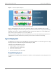
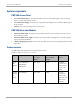
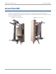
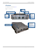
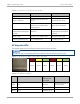
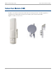
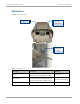
Table Of Contents
- Cambium
- PMP 450 Planning Guide
- Accuracy
- Copyrights
- Restrictions
- License Agreements
- High Risk Materials
- Safety and regulatory information
- Contents
- List of Figures
- List of Tables
- About This Planning Guide
- PMP support website: http://www.cambiumnetworks.com/support
- Cambium main website: http://www.cambiumnetworks.com/
- Sales enquiries: solutions@cambiumnetworks.com
- Email support: support@cambiumnetworks.com
- Cambium Networks
- 3800 Golf Road, Suite 360
- Rolling Meadows, IL 60008
- Chapter 1: Product description
- Chapter 2: Planning considerations
- Regulatory planning
- Network migration planning
- Site planning
- Link planning
- Analyzing the RF Environment
- Selecting Sites for Network Elements
- Diagramming Network Layouts
- Grounding and lightning protection
- Configuration options for TDD synchronization
- Data network planning
- Security planning
- Isolating APs from the Internet
- Managing module access by passwords
- Filtering protocols and ports
- Port Lockdown
- Isolating SMs
- Filtering management through Ethernet
- Allowing management from only specified IP addresses
- Configuring management IP by DHCP
- Planning for airlink security
- Planning for RF Telnet Access Control
- Planning for RADIUS integration
- Planning for SNMP security
- Ordering components
- Chapter 3: Legal information
- Cambium Networks end user license agreement
- Acceptance of this agreement
- Definitions
- Grant of license
- Conditions of use
- Title and restrictions
- Confidentiality
- Right to use Cambium’s name
- Transfer
- Updates
- Maintenance
- Disclaimer
- Limitation of liability
- U.S. government
- Term of license
- Governing law
- Assignment
- Survival of provisions
- Entire agreement
- Third party software
- Hardware warranty
- Limit of liability
- Cambium Networks end user license agreement
- Chapter 4: Reference information

PMP 450 Planning Guide Access Point (AP)
pmp-0047 (December 2012)
1-7
Table 2 AP interface descriptions and cabling
Interface Function Cabling
RF Port – Vertical Vertical RF connection to AP antenna 50 ohm RF cable, N-type
RF Port – Horizontal
Horizontal RF connection to AP
antenna
50 ohm RF cable, N-type
Sync/Default GPS synchronization signaling,
provides power to uGPS module.
Default plug port.
RJ11 cable or default plug
Power-over-Ethernet, Ethernet
communications (management
and data)
RJ45 cable
Power-over-Ethernet, Ethernet
communications (management
and data)
RF Port – FSK For future use in “Combo” mode 50 ohm RF cable, N-type
Ground Lug (bottom of unit) For grounding the unit 10 AWG copper wire
AP diagnostic LEDs
The diagnostic LEDs report the following information about the status of the module.
The LED color helps you distinguish position of the LED. The LED color does not indicate any status.
Figure 5 AP diagnostic LEDs, viewed from unit front
PWR SYN/1 SES/2 GPS/3 ACT/4 LNK/5
Table 3 AP LED descriptions
LED Color when active Status
information
provided
Notes
PWR red DC power
Always lit when power is
correctly supplied.
SYN/1 yellow Presence of sync Always lit on the AP.
SES/2 green Unused on the AP